
I. Key Operating Points for Disassembly and Assembly of the Valve Assembly
(1) Before removing valves and valve springs, mark each valve head in advance. The marking shall correspond to the cylinder number where the valve is installed (for example, for the valve of the 3rd cylinder, punch three dots on the valve head with a punch as identification).
In addition, components such as valve springs that must be matched to their original cylinders and cannot be mixed up shall be stored separately by cylinder after disassembly to avoid misassembly during subsequent reassembly. The rocker shaft and rockers are normally removed as a complete assembly; keep their assembled state intact during operation and avoid random disassembly.
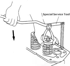
(2) For overhead valve (OHV) engines, a dedicated valve spring compressor must be used to disassemble and install valves. Compress the valve spring with the tool first, then remove or install the collets that fix the valve spring retainer, so as to complete disassembly or assembly of valves, springs and other parts. Refer to Figure 5-5-1 for the specific operation procedure.
If the dedicated valve spring compressor is unavailable on site, pry bars may be used to carefully compress the springs, or simple methods such as tapping with a socket wrench can be adopted to remove the collets and take off the valves and springs.
(3) For overhead camshaft (OHC) engines with more complex structures, preliminary steps shall be completed before removing the valve assembly: first release the tensioner load, then loosen the sprocket fastening bolts, and remove the timing chain and sprocket as an integrated unit from the camshaft. Special attention shall be paid to checking and confirming the alignment position of timing marks during this process, before proceeding to disassemble the valve assembly.
(4) The assembly procedure of the valve assembly shall generally follow the reverse sequence of disassembly. Extra caution is required when assembling the valve train of overhead camshaft engines: adjust the piston of the No.1 cylinder to the top dead center (TDC), and ensure the timing marks on the timing chain are precisely aligned and fully coincided with those on the sprockets.
II. Inspection and Repair Specifications for Valve Assembly
(I) Inspection and Repair Standards for Valves
(1) If grooves, abnormal width are formed on the valve working taper face due to wear, or spots and pits occur as a result of ablation, the taper face shall be refinished by valve grinding.
(2) An outside micrometer shall be used to accurately measure the wear of the valve stem. If the measured wear loss exceeds 0.05 mm, or obvious stepped wear marks can be felt by hand, the valve must be replaced with a new one.
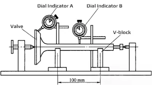
(3) The radial runout error of the valve head taper face relative to the cylindrical surface of the valve stem shall not exceed 0.03 mm, and the straightness error of the valve stem itself shall be no more than 0.02 mm. See Figure 5-5-2 for the specific inspection method. Cold pressing straightening can be adopted if the measured value exceeds the specified limit.
The straightness of the valve stem can also be inspected by rolling the valve back and forth on a surface plate, then measuring the clearance between the stem and the plate with a feeler gauge.
(4) If pits are formed on the lower end face of the valve stem due to wear, the end face shall be ground flat for repair.
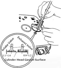
(5) After grinding repair, the margin thickness of the valve head must be maintained greater than 1 mm to guarantee structural strength.
(6) Valve grinding operations shall generally be carried out on a dedicated valve grinding machine. The primary purpose of this repair is to eliminate pitting and indentations on the working taper surface caused by ablation, restore a smooth and flat sealing surface, and improve sealing performance with the valve seat insert.
After valve grinding, carefully inspect the residual margin thickness of the valve head and the valve recess depth after installation (as shown in the following figure). If the measured values fall outside the limits specified in the service manual (refer to the corresponding engine operation manual for exact figures), the valve or valve seat insert shall be replaced.
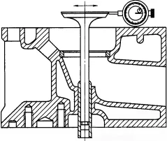
During long-term engine operation, the reciprocating motion of the valve stem inside the valve guide causes wear on the inner wall of the guide, gradually increasing the fit clearance between the valve stem and the guide. This weakens the guiding function of the valve guide and may result in incomplete valve closure, thereby impairing the normal operating performance of the engine.
Taking the CA6110 diesel engine as an example, the standard fit clearance between its valve stem and valve guide ranges from 0.025 mm to 0.056 mm (see Figure 5-5-4 for the inspection procedure), with a service limit of 0.15 mm. If the measured clearance exceeds this limit, either only the valve shall be replaced or both the valve and valve guide shall be replaced together, depending on the actual wear condition.
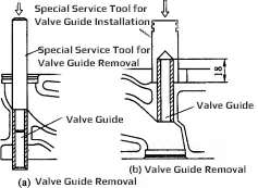
The operating procedures for replacing valve guides can be followed as illustrated in the above disassembly and assembly diagram.
1.Removal of Old Valve Guides
Use a stepped copper drift to punch or press out the worn valve guide. Keep the drift aligned with the central axis of the guide during operation to prevent damage to the guide bore in the cylinder head.
2. Selection of New Valve Guides
Accurately measure the outer diameter of the old guide with an outside micrometer. Select a new guide whose outer diameter is 0.01–0.04 mm larger than the old one to guarantee a reliable interference fit.
3. Installation of New Valve Guides
Coat the outer cylindrical surface of the new guide evenly with engine oil to facilitate pressing. Use a stepped copper drift to smoothly press the new guide into the guide bore of the cylinder head. After fitting, ensure the distance from the upper end face of the guide to the mounting surface of the valve spring retainer is 18 mm.
4. Reaming the Inner Bore of Valve Guide
If the measured fit clearance between the valve stem and guide bore is too small after installation, ream the inner bore with a dedicated valve guide reamer until the clearance meets technical specifications. Upon completion of reaming, insert the oil-lubricated valve stem into the guide and pull it up and down several times. Lift the valve and release it; the valve shall descend slowly and uniformly under its own weight.
(III) Repair of Valve Seat Inserts
Repair shall be carried out promptly when valve seat inserts suffer from wear, ablation or other defects. First, grind the working face of the valve seat; the maximum allowable grinding stock is 0.25 mm. If defects cannot be fully eliminated by grinding, install a new valve seat insert for restoration.
1. Fitting New Valve Seat Inserts
When installing seat inserts, bore the seat insert bore to specified dimensions via a vertical milling machine or special plane reamer, ensuring smooth and clean bore walls with roundness error no more than 0.0125 mm. Two methods are available for fitting inserts: heating the seat bore for thermal expansion, or cooling the insert for thermal contraction. The common method is heating the seat bore to approximately 100°C. Coat the outer wall of the seat insert with a sealing compound mixed of glycerin and red lead powder, place a soft metal spacer, then quickly punch the insert into the bore. An alternative method: immerse the seat insert in liquid nitrogen (-196°C) for 15–20 seconds, take it out rapidly and fit it into the seat bore.
2. Valve Seat Reaming
Valve seat reaming repair is required if the width of the valve seat working surface exceeds 2 mm due to wear, or if severe ablation pits appear on the working surface. Reamers are generally available in angles of 15°, 45° (or 30°) and 75°, and reaming is mostly performed manually. The detailed process is as follows:
(1) Select the pilot mandrel
Choose a matching reamer pilot mandrel according to the inner diameter of the valve guide. The mandrel shall slide into the guide smoothly without obvious radial play.
(2) Select the reamer
Select a reamer matching the specified angle of the valve seat and the diameter of the valve head, then fasten the reamer onto the taper section of the mandrel shaft.
(3) Rough reaming
Insert the mandrel fitted with the reamer into the valve guide bore. Hold the tool handle with both hands and rotate the reamer clockwise at a steady speed for reaming. Keep the reamer perpendicular during operation with even force and smooth rotation until all pits, indentations and other defects on the working surface are removed. If the reamer slips due to a cold-hardened layer on the working surface at the initial stage of reaming, place fine abrasive cloth under the reamer for preliminary grinding before continuing reaming.
(4) Trial fitting and contact surface trimming
After rough reaming, perform trial fitting with a reground valve or a new valve. The contact mark shall be located at the middle-lower section of the valve taper face, with a contact band width ranging from 1.5 mm to 2.0 mm. A wider contact band resists wear between the valve and seat but provides relatively poorer sealing performance; a narrower contact band ensures reliable sealing yet wears faster. In general, a wider contact band is adopted for valves with heavy valve spring pressure, while a narrower band is suitable for low spring pressure. If the contact mark shifts upward, use a 15° reamer to machine the upper edge of the valve seat to shift the contact area downward; If the contact mark shifts downward, use a 75° reamer to machine the lower edge of the valve seat to shift the contact area upward; If the contact band width exceeds 2 mm and its position is adjustable, re-trim with a 15° or 75° reamer as needed. If the contact band width is proper but the contact zone is significantly offset upward or downward beyond the adjustable range of reamers, the assembly can normally remain in service provided the contact area is more than 1 mm away from the edge of the valve taper face; otherwise, the valve or valve seat insert shall be replaced.
(5) Finish reaming
Finally, use a fine-tooth reamer with the same angle as the valve seat working surface for finish reaming. To achieve a smoother surface, place fine abrasive cloth under the reamer for final polishing.
(IV)Lapping of Valves and Valve Seats
Mutual lapping shall be performed to guarantee sealing performance under the following conditions: after grinding the valve working taper face; after replacement, reaming or grinding repair of valves and valve seats; or when slight ablation and pitting defects are detected between valves and valve seats during routine maintenance. Valve lapping can be implemented manually or by power-driven equipment (pneumatic or electric).
(1) Thoroughly clean the valves, valve seat inserts and valve guides to remove oil stains, carbon deposits and other contaminants from all contact surfaces, providing a clean environment for subsequent operations.
(2) For engines fitted with stellite heat-resistant hard alloy steel valve seat inserts, the material is hard and wear-resistant, so a bench grinder is generally adopted for finish machining to form an ideal mating surface, and traditional valve lapping is not required in principle. Nevertheless, valve seat inserts that have undergone reaming have relatively rough surfaces after machining, so a follow-up lapping procedure is mandatory to achieve satisfactory sealing performance.
(3) Before starting lapping, apply a thin, even layer of coarse lapping compound on the valve working taper face, and coat an appropriate amount of engine oil on the valve stem to lubricate the guide. Attach a rubber suction cup to the valve head, tap lightly up and down with moderate force while rotating the valve back and forth by approximately three-quarters of a full turn each cycle. During operation, adjust the relative contact position between the valve and valve seat by 10 to 15 degrees sequentially for uniform lapping. Control operating force at all times; excessive force shall be avoided to prevent surface damage or excessive wear.
(4) Terminate coarse lapping once a continuous, neat contact band free of spots and pits forms on the mating surfaces of the valve and valve seat. Rinse off residual coarse lapping compound and switch to fine lapping compound for fine finishing. When the contact band becomes uniformly bright and smooth, thoroughly clean the valves, valve seat inserts and guides again. Finally, apply a layer of clean lubricating oil and continue gentle lapping for several minutes before conducting the sealing test.
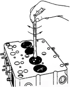
(V) Inspection of Sealing Performance for Valves and Valve Seats
To improve the sealing performance of valves and valve seats and guarantee the compression efficiency of engine cylinders, strict sealing inspection must be carried out after a series of finishing processes including valve grinding, seat reaming and mutual lapping. The common inspection methods for valve sealing performance are listed as follows:
Repair Technology for Marine Diesel Engines
1. Line Marking Method
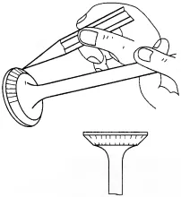
Draw clear circumferential lines on the lapped valve taper face with a soft pencil at an interval of approximately 4–5 mm (as shown in the following figure). Fit the valve into its matching valve seat, apply light pressure and twist the valve by about 30 degrees. Take out the valve and check the marks. If all pencil lines are neatly wiped off within the contact band of the valve seat, the sealing condition is qualified. If partial lines remain unbroken or fragmentary traces exist, poor sealing occurs at the corresponding position, and targeted re-lapping of the valve is required.
2. Tapping Test
Place the lapped valve lightly into its seat, then apply moderate impact force on the valve head by hand or with a special tool and tap several times. Take out the valve and closely examine the contact trace left on the valve seat. If a continuous, complete and bright annular band forms on the sealing surface without any gaps or dark spots, the sealing performance of the valve and valve seat meets the specification requirements.
3. Kerosene Leakage Test
Invert the cylinder head assembled with valves with the combustion chamber facing upward. Fill the combustion chamber with sufficient kerosene and let it stand for 5 minutes for observation. If no kerosene seeps through the joint between the valve and valve seat during this period, the sealing performance is qualified. If leakage occurs, reconditioning is required.
(VI) Inspection of Valve Springs
(1) The performance condition of valve springs exerts a critical influence on the operation of the entire engine valve train and overall engine performance. Broken, fatigued or under-tensioned valve springs will result in incomplete valve closure and abnormal operation, and may even trigger engine backfire and other malfunctions. For valve springs with a free height exceeding 50 mm, a new replacement spring must be installed if the measured free height is more than 3 mm shorter than the standard dimension, or if the spring force decays by more than 15% during testing.
(2) Stricter judgment criteria apply to valve springs with a free height below 50 mm. If the free height is reduced by more than 2 mm relative to the standard value, or the spring force decays by over 15%, the spring shall also be replaced to guarantee sufficient preload and operational reliability.
(3) Apart from length and spring force, spring perpendicularity is another key inspection item. Stand the spring upright on a surface plate and measure with a try square. If the perpendicularity error exceeds 3 mm over a 100 mm length, the spring is bent and deformed, which will impair normal operation and cause eccentric wear; such springs must be replaced.


