QSK50-G7 G-Drive Engine
CCEC QSK50-G7 (1500 RPM) Generator Drive Engine is V Type 16-Cylinder, 50.3 liters (3069 in3) Four-Strokes Engine with 159 mm (6.26 in) Bore and 159 mm (6.26 in) Stroke.
QSK50-G7 Generator Drive Engine Equipped with CMI MCRS Fuel System, Comes with Turbocharged and Aftercooled.The Standby Power for 50 Hz Generator Set (1500 RPM) of CCEC QSK50-G7 Generator Drive Engine is 2120 HP (1582 kW). The Prime Power for 50 Hz Generator Set (1500 RPM) of CCEC QSK50-G7 Generator Drive Engine is 1905 HP (1421 kW).The Continuous Power for 50 Hz Generator Set (1500 RPM) of CCEC QSK50-G7 Generator Drive Engine is 1680 HP (1253 kW).
As Part of EMAC, SinoGen Also Provide Complete Power Supply Solutions that Powered by CCEC, Our Ranges of Products Including Open Type Generator Set, Silence Type Generator Set, Super Silence Type Generator Set, Mobile Trailer, Complete Power Truck and Complete Power Car for Railways Applications.
We Provide Full Life Cycle Services for All Customers, From Design to Power System Supply, from Installation to Commissioning, from After-Sales Service Training to Spare Parts Supply, From Trouble Shooting to Overhaul Technical Support.
Advantages of CCEC QSK50-G7 G-Drive Engine
-
High quality alloy cast iron for the rigidity performance and lower vibration and noise. Wet and replaceable cylinder liners for better heat rejection performance and easier replacement.
-
4 valves per cylinder, Optimize the mixed level which lead to an excellent fuel consumption rate and emission performance. High quality alloy cast iron, one cylinder one head, single camshaft and special designed outine for better reliability and durability.
-
CMS unique PT with fixture and Step Timing control for precise fuel injection make the fuel injection pressure above 120 Mpa, which leads to an excellent fuel consumption rate and emission performance. Check valve in fuel tube improve reliability.
-
Gear water pump and great flux channel design provide effective cooling. Spin-in water filter makes the coolant clean and keeps it in normal acidity.
-
Advanced Holset turbocharger and after-cooled technology, pulse exhaust manifold reduce exhaust temperature, provide excellence fuel consumption and emission performance.
Technical Specifications
Basic Introduction of CCEC QSK50-G7 G-Drive Engine
| Engine Model: | QSK50-G7 |
| Engine Type: | 6-Cylinder ; Vee ; 4-Cycle |
| Displacement: | 50.3 L |
| Rated Power / Speed: | 1421 kW @ 1500 RPM |
| Aspiration Method: | Turbocharged and Aftercooled |
| Emission Standard: | U.S. EPA Tier 2, CARB Tier 2 |
| Bore * Stroke: | 159 mm * 159 mm |
| Packing Size (L * W * H): | 2794 mm * 1507 mm * 1846 mm |
| Dry Weight: | 5410 kg |
| Lead Time: | 15-30 Working Days |
| Payment Terms: | T / T ,L / C |

Engine Model |
Prime Power |
Aspiration |
Configuration |
Performance Curve |
Compression Ratio |
| QSK50-G7 | 1905 HP (1421 kW) at 1500 RPM | Turbocharged and Aftercooled | D283039GX03 | FR – 6837 | 15.0 : 1 |
| ——END—— | |||||
General Information of CCEC QSK50-G7 Generator Drive Engine |
|||
| Engine Model | QSK50-G7 | Configuration | D283039GX03 |
| Prime Power | 1905 HP (1421 kW) at 1500 RPM | CPL No. | 3625 |
| Continuous Power | 1680 HP (1253 kW) at 1500 RPM | Compression Ratio | 15.0 : 1 |
| Standby Power | 2120 HP (1582 kW) at 1500 RPM | Fuel System | CMS MCRS |
| Emission Certificatio | U.S. EPA Tier 2, CARB Tier 2 | Displacement | 50.3 L (3,069 in3) |
| Aspiration | Turbocharged and Aftercooled | Type | 6-Cylinder ; Vee ; 4-Cycle |
| Bore x Stroke | 6.26 in. * 6.26 in. / 159 mm * 159 mm | ||
Installation Data of CCEC QSK50-G7 Generator Drive Engine |
|||
| Dry Weight (Approximate) | 11,927 lb. / 5,410 kg | ||
| Wet Weight (Approximate) | 12,593 lb. / 5,712 kg | ||
| Moment of Inertia of Rotating Components -With FW 6066 Flywheel | 112 in·lbf·sec2 / 12.7 kg·m2 | ||
| Center of Gravity from Rear Face of Block | 47.48 in. / 1,206 mm | ||
| Center of Gravity Above Crankshaft Centerline | 10.98 in. / 279 mm | ||
| Maximum Bending Moment at Rear Face of Block | 4,499 lb·ft / 6,100 N.m | ||
| ——END—– | |||
Engine Performance Data 1500 RPM / 50 HZ of CCEC QSK50-G7 Generator Drive Engine |
|||||
| Standby Power | Prime Power | Standby Power | Prime Power | ||
| Governed Engine Speed | 1500 RPM | 1500 RPM | Exhaust Gas Flow | 10576 cfm / 4991 L/s | 9671 cfm / 4564 L/s |
| Engine Idle Speed | 700 – 900 RPM | 700 – 900 RPM | Air to Fuel Ratio -air : fuel | 25.5 : 1 | 26.5 : 1 |
| Gross Engine Power Output | 2120 HP / 1581 kW | 1905 HP / 1421 kW | Radiated Heat to Ambient | 8693 BTU/min / 153 kW | 7793 BTU/min / 137 kW |
| Brake Mean Effective Pressure | 365 psi / 2515 kpa | 328 psi / 2260 kpa | Heat Rejection to Jacket Coolant | 32216 BTU/min / 566 kW | 29879 BTU/min / 525 kW |
| Piston Speed | 1875 ft/min / 9.5 m/s | 1562 ft/min / 7.9 m/s | Heat Rejection to Exhaust | 64961 BTU/min / 1142 kW | 57643 BTU/min / 1014 kW |
| Friction Horsepower | 235 HP / 175 kW | 235 HP / 175 kW | Heat Rejected to *Fuel | 475 BTU/min / 8.4 kW | 475 BTU/min / 8.4 kW |
| 4 psi Friction Head | 448 gpm / 1695 L/min | 448 gpm / 1695 L/min | Heat Rejection to Aftercooler Coolant | 21052 BTU/min / 370 kW | 18229 BTU/min / 321 kW |
| Maximum Friction Head | 416 gpm / 1574 L/min | 416 gpm / 1574 L/min | 2 psi Friction Head | 123 gpm / 466 L/min | 123 gpm / 466 L/min |
| Intake Air Flow | 4234 cfm / 1998 L/s | 3944 cfm / 1861 L/s | Maximum Friction Head | 121 gpm / 458 L/min | 121 gpm / 458 L/min |
| Exhaust Gas Temperature – Dry Stack | 928 °F / 498 °C | 893 °F / 478 °C | |||

System Technical Data of CCEC QSK50-G7 Generator Engine |
||
| Exhaust System | Maximum Back Pressure at Standby Power | 2 in.Hg / 6.8 kPa |
| Air Induction System | Maximum Allowable Intake Air Restriction With Dirty Filter Element | 25 in.H2O / 6.2 kPa |
| Maximum Allowable Intake Air Restriction With Normal Duty Air Cleaner and Clean Filter Element | 15 in.H2O / 3.7 kPa | |
| COOLING SYSTEM | Coolant Capacity – Engine Only | 148 quarts / 140.1 litre |
| Minimum Pressure Cap Rating at Sea Level | 14 PSI / 97 kPa | |
| Maximum Static Head of Coolant Above Crankshaft Centerline | 60 ft. / 18.3 m | |
| Maximum Top Tank Temperature (Maximum Top Tank Temp) for Standby Power/Prime Power | 220 /212 °F / 104/100 °C | |
| Thermostat (Modulating) Range | 180 – 200 °F / 82 – 93 °C | |
| Lubrication System | Oil Pressure @ Minimum Idle Speed | 20 PSI / 138 kPa |
| Oil Pressure @ Governed Speed | 50 – 70 PSI / 350 – 485 kPa | |
| Maximum Oil Temperature | 250 °F / 121 °C | |
| Oil Capacity with OP 6100 Oil Pan : Low – High | 46 – 54 U.S. Gal / 174.1 -204.4 liter | |
| Total System Capacity (with Combo Filter) | 62 U.S. gal / 234.7 L | |
| Fuel System | Type Injection System | CMS |
| Maximum Fuel Supply Restriction at Fuel Pump Inlet (clean/dirty filter) | 5 / 9 in Hg / 16.9 / 30 kPa | |
| Maximum Allowable Head on Injector Return Line (Consisting of Friction Head and Static Head) | 10 in Hg / 34 kPa | |
| Maximum Fuel Inlet Temperature | 160 °F / 71 °C | |
| Maximum Supply Fuel Flow – 1500 RPM | 222 US gph / 840 litre/hr | |
| Maximum Return Fuel Flow – 1500 RPM | 116 US gph / 439 litre/hr | |
| ELECTRICAL SYSTEM | System Voltage | 24 volt |
| Minimum Recommended Battery Capacity @ Cold Soak at 50 ℉(10 ℃) and Above | 1800 CCA | |
| Minimum Recommended Battery Capacity @ Cold Soak at 32 ℉-50 ℉(0 ℃-10 ℃) | 1800 CCA | |
| Minimum Recommended Battery Capacity @ Cold Soak at 0 ℉-32 ℉(-18 ℃-0 ℃) | 1800 CCA | |
| Maximum Starting Circuit Resistance | 0.002 Ohm | |
| Cold Start Capability | Unaided Cold Start –Minimum Cranking Speed | 150 RPM |
| Unaided Cold Start –Minimum Ambient Temp for Unaided Cold Start | 7.2 °C / 45 °F | |
| ——END—— | ||
Scopes of Supply of CCEC QSK50-G7 Generator Drive Engine |
|||
| Air Intake System | 1. Air Intake Manifold | Exhuast System | 1. Exhuast Manifold |
| 2. Standard Air Filter | 2. Turbocharger | ||
| 3. Water-Air Intercooler | 3. Exhuast Elbow | ||
| Starting System | 1. Starter Motor | Charging System | 1. Charging Alternator |
| 2. Starter Rely | |||
| Lubricating System | 1. Oil Pump | Cooling System | 1. Water Pump |
| 2. Oil Filter | 2. Engine Fan | ||
| 3. Standard Radiator | |||
| Engine Shut-Down System | 1. Engine Fuel Shut-Off Solenoid | Power Output System | 1. Flywheel |
| 2. Standard Flywheel Housing | |||
| Fuel System | 1. Fuel Transfer Pump | ||
| 2. High-Pressure Fuel Pump | |||
| 3. Fuel Filter | |||
| ——END—— | |||
Optional Accessories of CCEC QSK50-G7 Generator Drive Engine |
|||
| Air Intake System | 1. Air Intake Pre-Heater | Exhuast System | 1. Muffler & Bellows |
| 2. Air Intake Shut-Off Valve | 2. Spark Arrestor Type Muffler & Bellows | ||
| 3. Heavy-Duty Air Filter | 3. DPF System | ||
| 4. Plateau Type Air Filter | |||
| Fuel System | 1. Coarse Filter | Lubricating System | 1. Oil Pre-Heater |
| 2. Fuel Pre-Heater | |||
| Starting System | 1. Manual Magnetic DC Contactor | Cooling System | 1. Silent Type Radiator |
| 2. Dual Ears Flywheel Housing | 2. Plateau Radiator | ||
| 3. Spring Starter Motor | 3. Salt-Spray Resistant Radiator | ||
| 4. Air Starter Motor | 4. Coolant Pre-Heater | ||
| 5. Hydraulic Starter Motor | 5. Jacket Water Heater | ||
| 6. Manual Magnetic DC Contactor | |||
| ——END—— | |||
As part of EMAC, SinoGen focusing on generator set related business, from Generator drive engine power pack to complete generator set, from generator control panel to synchronizing cabinet, from super silent type generator set to mobile power trailer, SinoGen provides professional one-stop solution for everything customer needed for generator set.
For more information of our complete generator set products, you are welcome to visit SinoGen homepage: www.sino-gen.com
Modifiable components of QSK50-G7 Generator Drive Engine |
|||
| Air Intake System | 1. Installation Position of Air Filter | Charging System | 1. 12 V Charging Alternator for 12 V Electric System |
| 2. Upgrade to Heavy-Duty Type Air Fitler | 2. Explosion-Proof Charging Alternator | ||
| Exhuast System | 1. Position of Turbocharger | Lubricating System | 1. Oil Pan Position |
| 2. Water-Cooled Exhuast Manifold | 2. Number of Dipstick | ||
| 3. Water-Cooled Turbocharger | 3. Position of Dipstick | ||
| Fuel System | 1. Upgrade to Fuel Fitler that Integrated with Fuel Transfer Pump | Starting System | 1. 12 V Starter Motor for 12 V Electric System |
| Engine Shut-Down System | 1. 12 V Solenoid for 12 V Electric System | Power Output System | 1. Size of Flywheel Housing and Flywheel. |
| 2. Explosion-Proof Solenoid | 2. Dual-Ear Flywheel Housing (For Twin-Starter System) | ||
| ——END—— | |||
Note: All Above Data are Just for Reference, All Data Might Change Without Notices or Updates, Please Contact Our Sales Team to Confirm All Details Via WhatsApp or Email.

Engine Sale Manual

Installation Drawing

Installation Manual

Operation Manual

Parts Catalogue


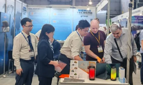


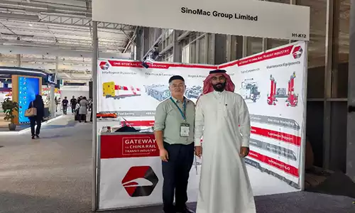
![Deeply Cultivate the International Market, Empowering the Future of Rail ——Focus [PROMotion Expo 2025] SinoMac Exhibition Highlights Review](https://ccec-engine.com/wp-content/uploads/2025/09/Deeply-Cultivate-the-International-Market-Empowering-the-Future-of-Rail-——Focus-PROMotion-Expo-2025-SinoMac-Exhibition-Highlights-Review.webp)