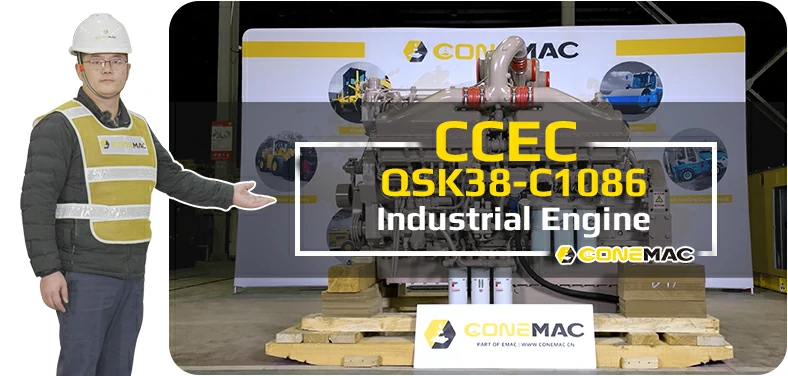
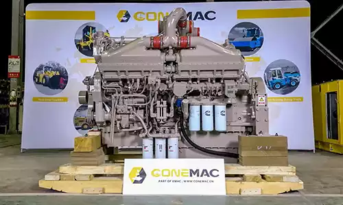
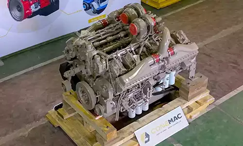
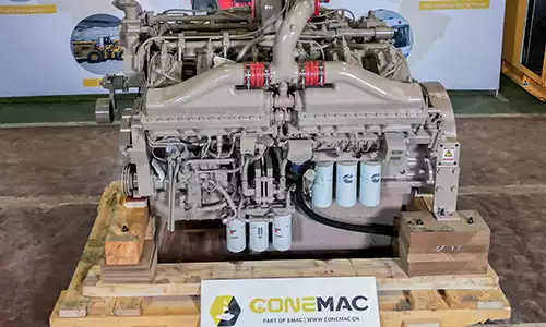
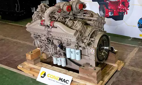
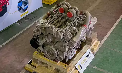
QSK38-C1086 Industrial Engine
CCEC QSK38-C1086 (1800 RPM) Industrial Engine is V type 12-cylinder, 37.7 liters four-strokes engine with 159 mm (6.25 in) bore and 159 mm (6.25 in) stroke.
QSK38-C1086 Pump Drive Engine equipped with CCECModular Common Rail Fuel System, comes with turbocharged aftercooler, with a EURO II post-processor. The Advertised power at 1800 RPM of CCEC QSK38-C1086 Industrial Engine is 1086 HP (810 kW). The maximum torque of the engine at 1350 RPM is 4869 N.m.
As part of EMAC, ConeMac provides industrial power pack solution that integrated with air intake, air exhaust, cooling system, control system, transmission and hydraulic accessories, We also supplying special products such as explosion proof engine, generator and water pump set, as well as ultra-low temperature condition engine power pack.
We provide full life cycle services for all customers, from design to power system supply, from installation to commissioning, from after-sales service training to spare parts supply, from trouble shooting to overhaul technical support.
Advantages of CCEC QSK38-C1086 Industrial Engine
-
Lower oil consumption, Extended stroke, the expansion of the combustion gas more fully, Increase effective efficiency output, the economy is better.
-
Strong power, advanced 4 air valves structure, greater horsepower, air burning more thoroughly, while making low speed torque increase, quicken response speedily, climb strongly.
-
Excellent reliability, with compulsive cold cut articulated pistons, Can bear extreme high mechanical load and heat load, Strength can be comparable with heavy engine.
-
Better emissions, Decorate injector and symmetrical combustion chamber in center, make the cylinder is more homogeneous mixture, burning more fully, lower emissions.
-
Super life, 30 % engines 800,000 km without overhaul.
-
Excellence power, Clean burning, use the advanced lean-burn closed loop electronic control system.
-
Excellent cold start performance, equipped with air suction electric preheater and 7.8 kW power starter, completely improve the cold start performance of the engine. Through the arctic village-MoHe of China -36 °C extreme low temperature validation.
Technical Specifications
Basic Introduction of CCEC QSK38-C1086 Industrial Engine
| Engine Model: | QSK38-C1086 |
| Engine Type: | V 12 Cylinder 4 Stroke 4 Valve |
| Displacement: | 37.7 L |
| Rated Speed: | 1800 RPM |
| Rated Power / Speed: | 1086 HP @ 1800 RPM |
| Aspiration Method: | Turbocharged Aftercooled |
| Emission Standard: | U.S. EPA Tier 2 |
| Bore * Stroke: | 159 mm * 159 mm |
| Packing Size (L * W * H): | 2260 mm * 1339 mm * 2332 mm |
| Wet Weight: | 4842 kg |
| Lead Time: | 15-30 Working Days |
| Payment Terms: | T/T ,L/C |


Engine Model |
Advertised power |
Peak Torque |
Curve & Datasheet |
Compression Ratio |
Fuel System |
| QSK38-C1085 | 1085 HP @ 1800 RPM | 3591 lb ft (4869 N m) @ 1350 RPM | FR 6780 | 15.0 : 1 | MCRS |
| QSK38-C1086 | 1086 HP @ 1800 RPM | 3591 lb ft (4869 N m) @ 1350 RPM | FR 6780 | 15.0 : 1 | Cummins MCRS |
| QSK38-C1200 | 1200 HP @ 1800 RPM | 3861 lb ft (5235 N m) @ 1400 RPM | FR 6779 | 15.0 : 1 | MCRS |
| QSK38-C1260 | 1260 HP @ 1800 RPM | 4054 lb ft (5496 N m) @ 1400 RPM | FR 6735 | 15.0 : 1 | MCRS |
| QSK38-C1350 | 1350 HP @ 1800 RPM | 4321 lb ft (5858 N m) @ 1500 RPM | FR 6904 | 15.0 : 1 | MCRS |
| QSK38-C1530 | 1530 HP @ 1800 RPM | 4604 lb ft (6242 N m) @ 1500 RPM | FR 60240 | 15.0 : 1 | MCRS |
| QSK38-C1600 | 1600 HP @ 1900 RPM | 4604 lb ft (6242 N m) @ 1500 RPM | FR 6869 | 15.0 : 1 | Cummins MCRS |
| ——END—— | |||||
General Information of DCEC QSK38-C1086 Industrial Engine |
|||
| Engine Model | QSK38-C1086 | CPL Code | 3380 |
| Curve & Datasheet | FR6780 | Rated Power | 1086 HP (810 kW) @ 1,800 RPM |
| Compression Ratio | 15.0 : 1 | Torque Peak | 3591 lb-ft (4869 N-m) @ 1,350 RPM |
| Noise Emissions Top Side | 105.1 dBa | Revision | 9-Mar-15 |
| Noise Emissions Right Side | 101.6 dBa | Displacement | 2300 in3 ( 37.7 L ) |
| Noise Emissions Left Side | 101.8 dBa | Fuel System | Cummins MCRS |
| Noise Emissions Front Side | 102.4 dBa | Maximum low idle speed | 1400 RPM |
| Exhaust noise emissions | 94.3 dBa | Minimum low idle speed | 600 RPM |
| Aspiration | Turbocharged Aftercooled | Minimum engine speed for full load sustained operation | 1700 RPM |
| Configuration | D233040CX03 | Emission Certification | U.S. EPA Tier 2 |
| ——END—— | |||
Torque Output |
Power Output |
Fuel Consumption |
||||||
| RPM | lb-ft | N-m | RPM | HP | kW | RPM | lb/HP-hr | g/kW-hr |
| 600 RPM | 2050 lb-ft | 2779 N-m | 600 RPM | 234 HP | 174 kW | 1350 RPM | 0.371 lb/HP-hr | 226 g/kW-hr |
| 800 RPM | 2550 lb-ft | 3457 N-m | 800 RPM | 388 HP | 289 kW | 1400 RPM | 0.372 lb/HP-hr | 226 g/kW-hr |
| 1000 RPM | 3000 lb-ft | 4067 N-m | 1000 RPM | 571 HP | 426 kW | 1500 RPM | 0.363 lb/HP-hr | 221 g/kW-hr |
| 1200 RPM | 3425 lb-ft | 4644 N-m | 1200 RPM | 783 HP | 584 kW | 1600 RPM | 0.352 lb/HP-hr | 214 g/kW-hr |
| 1350 RPM | 3590 lb-ft | 4867 N-m | 1350 RPM | 923 HP | 688 kW | 1700 RPM | 0.348 lb/HP-hr | 212 g/kW-hr |
| 1400 RPM | 3560 lb-ft | 4827 N-m | 1400 RPM | 949 HP | 708 kW | 1800 RPM | 0.352 lb/HP-hr | 214 g/kW-hr |
| 1500 RPM | 3500 lb-ft | 4745 N-m | 1500 RPM | 1000 HP | 746 kW | |||
| 1600 RPM | 3425 lb-ft | 4644 N-m | 1600 RPM | 1043 HP | 778 kW | |||
| 1700 RPM | 3325 lb-ft | 4508 N-m | 1700 RPM | 1076 HP | 802 kW | |||
| 1800 RPM | 3169 lb-ft | 4297 N-m | 1800 RPM | 1086 HP | 810 kW | |||
| —END— | ||||||||
Performance Data DCEC QSK38-C1086 Industrial Engine |
||||||
| Advertised power | Governed Power | Peak Torque | ||||
| Engine Speed | 1800 RPM | N/A | 1350 RPM | |||
| Output Power | 1086 HP | 810 kW | N/A | N/A | 923 HP | 688 kW |
| Torque output | 3169 lb-ft | 4,297 N-m | N/A | N/A | 3591 lb-ft | 4869 N-m |
| Friction horsepower | 162 HP | 121 kW | N/A | N/A | 97 HP | 72 kW |
| Intake Manifold Pressure | 49 in-Hg | 165 kPa | N/A | N/A | 44 in-Hg | 150 kPa |
| Turbo Comp. Outlet Pressure | 49 in-Hg | 167 kPa | N/A | N/A | 45 in-Hg | 152 kPa |
| Turbo Comp. Outlet Temperature | 315 °F | 157 °C | N/A | N/A | 310 °F | 154 °C |
| Inlet Air Flow | 2712 ft³/min | 1280 L/s | N/A | N/A | 1929 ft³/min | 910 L/s |
| Exhaust Gas Flow | 6236 ft³/min | 2943 L/s | N/A | N/A | 5654 ft³/min | 2668 L/s |
| Exhaust Gas Temperature | 823 °F | 439 °C | N/A | N/A | 1019 °F | 548 °C |
| Heat rejection to ambient air | 4081 BTU/min | 72 kW | N/A | N/A | 3655 BTU/min | 64 kW |
| Heat rejection to exhaust gas | 39024 BTU/min | 686 kW | N/A | N/A | 37072 BTU/min | 652 kW |
| Heat rejection to LTC coolant | 8805 BTU/min | 155 kW | N/A | N/A | 6217 BTU/min | 109 kW |
| Heat rejection to HTC coolant | 18594 BTU/min | 327 kW | N/A | N/A | 18327 BTU/min | 322 kW |
| ——END—— | ||||||
System Technical Data of DCEC QSK38-C1086 Industrial Engine |
|||
| Intake Air System | Maximum air temperature rise over ambient at turbocharger compressor inlet | 20 delta °F | 11.1 delta °C |
| Maximum Intake Air Restriction With Clean Filter | 15 in-H2O | 3.7 kPa | |
| Maximum Intake Air Restriction With Dirty Filter | 25 in-H2O | 6.2 kPa | |
| Minimum air cleaner dirt holding capacity | 25 g/cfm | ||
| Maximum intake air bleed for accessories (not including air compressor) | 0 ft3/min | 0 L/s | |
| Recommended intake piping size (inner diameter) | 6.0 in | 152 mm | |
| Exhaust System | Maximum exhaust restriction | 3 in-Hg | 10 kPa |
| Recommended exhaust piping size (inner diameter) | 7.79 in | 198 mm | |
| Maximum static bending moment at turbocharger outlet flange | 20 lb-ft | 27.1 N-m | |
| Lubrication System | Nominal operating oil pressure at minimum low idle speed | 30 psi | 207 kPa |
| Nominal operating oil pressure at advertised speed | 70 psi | 483 kPa | |
| Minimum oil pressure within 4 seconds of engine first firing at minimum low idle speed (measured at turbocharger oil inlet) | 20 psi | 138 kPa | |
| Maximum Oil Flow to All Accessories | N/A | ||
| Maximum Oil Pressure Spike on Cold Engine | N/A | ||
| Fuel System | Maximum Heat Rejection to Return Fuel Which Occurs at The Following Conditions | 298 BTU/min | 5 kW |
| Maximum Heat Rejection to Return Fuel Which Occurs at The Following Conditions Fuel Return Flow | 572 lb/hr | 259 kg/hr | |
| Maximum Heat Rejection to Return Fuel Which Occurs at The Following Conditions Fuel Return Temperature (Prior to Fuel Cooler) | 173 °F | 78 °C | |
| Maximum Fuel Supply Flow | 956 lb/hr | 434 kg/hr | |
| Maximum Fuel Return Flow | 572 lb/hr | 259 kg/hr | |
| Maximum Fuel Supply Temperature (MeAsured at On-Engine Fuel Inlet Fitting) | 160 °F | 71 °C | |
| Maximum Fuel Supply Pressure (MeAsured at On-Engine Fuel Inlet Fitting) | 5 psi | 34 kPa | |
| Maximum Fuel Return Restriction (MeAsured at On-Engine Fuel Drain Fitting) | 10 in-Hg | 34 kPa | |
| Fuel System Stage 1 filter(s) | Maximum Combined Fuel Supply Restriction of Stage 1 Assembly & Oem Plumbing (MeAsured at On-Engine Fuel Inlet Fitting) With Clean Stage 1 Fuel Filter(S) at Maximum Fuel Supply Flow | 5 in-Hg | 16.9 kPa |
| Maximum Combined Fuel Supply Restriction of Stage 1 Assembly & Oem Plumbing (MeAsured at On-Engine Fuel Inlet Fitting) With Dirty Stage 1 Fuel Filter(S) at Maximum Fuel Supply Flow | 10 in-Hg | 33.8 kPa | |
| Nominal Restriction of Clean Stage 1 Fuel Filter Assembly at Maximum Fuel Supply Flow | 2 in-Hg | 7 kPa | |
| Maximum Fuel Inlet Pressure MeAsured at Stage 1 Inlet | N/A | ||
| Recommended Maximum Fuel Inlet Pressure For Seeing Is Believing® (MeAsured at Stage 1 Inlet) | N/A | ||
| Cooling System | Cooling system type | 2 Pump-2 Loop | |
| Cooling Systems Requirements of both LTC and HTC cooling circuits | Minimum fill rate | 5 gpm | 19 L/min |
| Maximum deaeration time | 25 min | ||
| Acceptable types of deaeration systems | Fully deaerating | ||
| Minimum water pump inlet pressure with fully deaerating cooling system | 10 in-Hg | 34.47379 kPa | |
| Minimum pressure cap rating at sea level | 11 psi | 76 kPa | |
| Maximum pressure cap rating at sea leve | 15 psi | 103 kPa | |
| Minimum coolant expansion space (% of total cooling system capacity | 6 % | ||
| Minimum drawdown (% of total cooling system capacity) | 11 % | ||
| Cooling Systems High Temperature Circuit (HTC) | LTC coolant volume (engine only) | 24 quarts | 23 L |
| LTC thermostat opening temperature | 115 °F | 46 °C | |
| LTC thermostat fully open temperature | 135 °F | 57 °C | |
| Maximum LTC water pump inlet temperature at 77 °F (25 °C) ambient air temperature | 120 °F | 49 °C | |
| Maximum LTC water pump inlet temperature at LAT | 165 °F | 74 °C | |
| Maximum external LTC restriction at 1800 RPM | 5 psi | 35 kPa | |
| Electrical System | System voltage | 24 V | |
| Minimum battery capacity for engine only [cold soak at 0 °F (-18 °C) or above] cold cranking amperes (CCA) | 1,800 CCA | ||
| Minimum battery capacity for engine only [cold soak at 0 °F (-18 °C) or above] reserve capacity (RC) | 640 min | ||
| Cranking System (Cold Starting Capability) | Minimum cranking speed: | 150 RPM | |
| Unaided Cold Start Minimum ambient temperature | 10 °F | -12 °C | |
| Aided Cold Start Minimum ambient temperature with only ether | -26 °F | -32 °C | |
| Aided Cold Start Minimum ambient temperature with only coolant and oil heaters | -26 °F | -32 °C | |
| —END— | |||
Scopes of Supply of CCEC QSK38-C1086 Industrial Engine |
||||
| Air Intake System | 1. Air Intake Manifold | Exhaust System | 1. Exhuast Manifold | |
| 2. Water-air Intercooler | 2. Turbocharger | |||
| 3. N/A | 3. Exhuast Elbow | |||
| Fuel System | 1. Fuel transfer pump | Starting System | 1. Starter motor | |
| 2. High-pressure fuel pump | 2. Starter Relay | |||
| 3. Fuel Filter | 3. N/A | |||
| Charging System | 1. Charging alternator | Engine Shut-Down System | 1. Engine fuel shut-off solenoid | |
| Lubricating System | 1. Oil pump | Cooling System | 1. Water pump | |
| 2. Oil filter | 2. Engine Fan | |||
| 3. N/A | 3. Standard radiator | |||
| Power Output System | 1. Flywheel | Engine Mounting System | 1. Engine Mounting Bracket | |
| 2. Standard flywheel housing | 2. N/A | |||
| Engine Auiliary Accessories | 1. Air compressor | |||
| 2. Power steering pump | ||||
| ——END—— | ||||
Optional Accessories of CCEC QSK38-C1086 Industrial Engine |
||||
| Air Intake System | 1. Air Intake pre-heater | Exhuast System | 1. Muffler & bellows | |
| 2. Air intake shut-off valve | 2. Flame trap | |||
| 3. Air filter | 3. Spark arrestor type Muffler & bellows | |||
| 4. Air intake pre-filter | 4. DPF system | |||
| 5. Air filter alarm system | 5. N/A | |||
| Fuel System | 1. Coarse Filter | Starting System | 1.Manual Magnetic DC Contactor | |
| 2. Fuel pre-heater | 2. Dual ears flywheel housing | |||
| 3. N/A | 3. Spring Starter Motor | |||
| 4. N/A | 4. Air Starter Motor | |||
| 5. N/A | 5. Hydraulic Starter Motor | |||
| Lubricating System | 1. Oil pre-heater. | Cooling System | 1. Silent Type Radiator | |
| 2. N/A | 2. Plateau Radiator | |||
| 3. N/A | 3. Salt-Spray Resistant Radiator | |||
| 4. N/A | 4. Coolant pre-heater | |||
| Power Output System | 1. Clutch | Engine Mounting System | 1. Shock absorber pad | |
| Engine Auiliary Accessories | 1. Hydraulic oil pump | Control System | 1. Can add mechanical accelerator pedal | |
| 2. Air conditioner compressor | 2. N/A | |||
| 3. N/A | 3. N/A | |||
| ——END—— | ||||
As part of EMAC, PumpMac focusing on water pump set related business, from pump drive engine, to WPT PTO, from complete engine power pack to complete water pump set, from NFPA20 standard fire fighting pump accessories to fire pump drive package, from explosion proof accessories to complete explosion-proof water pump set, PumpMac provides professional one-stop solution for everything customer needed for water pump set industry.
For more information of our pump drive power pack and complete water pump set products, you are welcome to visit PumpMac homepage: www.pumpmac.com
Modifiable Components of CCEC QSK38-C1086 Industrial Engine |
||||
| Air Intake System | 1. Installation position of air filter | Exhuast System | 1. Can modify installation position and direction of | |
| 2. Upgrade to heavy-duty type air fitler | turbocharger | |||
| 3. N/A | 2. Water-cooled exhuast manifold | |||
| 4. N/A | 3. Water-cooled turbocharger | |||
| Fuel System | 1. Upgrade to fuel fitler that integrated with fuel transfer | Starting System | 1. 12 V starter motor for 12 v electric system | |
| pump and fuel pre-hearter | 2. Upgrading to specified brand and speicifications of | |||
| 2. N/A | starter motor | |||
| Charging System | 1. 12 V charging alternator for 12 v electric system | Engine Shut-Down System | 1. 12 V solenoid for 12 v electric system | |
| 2. Explosion-proof charging alternator | 2. Explosion-proof solenoid | |||
| 3. Upgrading to specified brand and speicifications of | 3. N/A | |||
| charging alternator | 4. N/A | |||
| Lubricating System | 1. Oil Pan position | Cooling System | 1. Can modify engine fan into blower fan or suction fan | |
| 2. Number of dipstick | 2. Can modify central position of engine cooling fan | |||
| 3. Position of dipstick can choose from 6 positions | 3. Can choose type of engine fan from mechanical type or | |||
| 4. Can modify oil filter to be remote installation | electric type | |||
| Power Output System | 1. Can modify size of flywheel housing and flywheel. | Engine Mounting System | 1. Can modify engine mouting bracket. | |
| 2. Dual-ear flywheel housing (For twin-starter system) | 2. N/A | |||
| 3. Some of models can modify flywheel housing into PTO | 3. N/A | |||
| integrated type. | 4. N/A | |||
| 4. Engine have connecting port of PTOs, that able to | 5. N/A | |||
| provide power output. | 6. N/A | |||
| Engine Auiliary Accessories | 1. All of auxiliary system can choose specified brands and | |||
| specifications. | ||||
| 2. Additional auxiliary systems can be added for special | ||||
| applications. | ||||
| ——END—— | ||||
Note: All Above Data are Just for Reference, All Data Might Change Without Notices or Updates, Please Contact Our Sales Team to Confirm All Details Via WhatsApp or Email.

Engine Sale Manual

Installation Drawing

Installation Manual

Operation Manual

Parts Catalogue


![Deeply Cultivate the International Market, Empowering the Future of Rail ——Focus [PROMotion Expo 2025] SinoMac Exhibition Highlights Review](https://ccec-engine.com/wp-content/uploads/2025/09/Deeply-Cultivate-the-International-Market-Empowering-the-Future-of-Rail-——Focus-PROMotion-Expo-2025-SinoMac-Exhibition-Highlights-Review.webp)