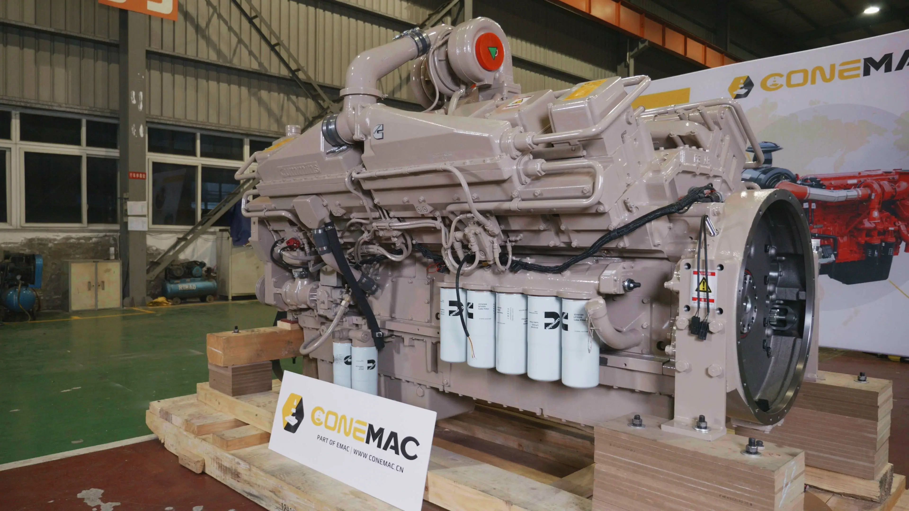
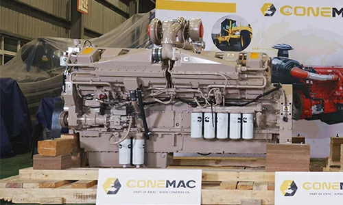
KTA50-C2250 Industrial Engine
CCEC KTA50-C2250 (1900 RPM) Industrial Engine is V type16-cylinder, 50.3 liters four-strokes engine with 159 mm (6.25 in) bore and 159 mm (6.25 in) stroke.
KTA50-C2250 Industrial Engine equipped with PT Fuel System, comes with Turbocharged, Low Temperature Aftercooled. The governed power of the CCEC KTA50-C1600 industrial engine is 2250 HP (1679 kW) at 1900 RPM, and the governed torque of the engine at 1900 RPM in this mode is 8439 N.m(6226 lb.ft). The Peak Torque of the CCEC KTA50-C2250 industrial engine is 1864 HP (1390 kW) at 1500 RPM, and the torque of the engine at 1500 RPM in this mode is 8849 N.m(6529 lb.ft).
To achieve different output, CCEC K50 series Industrial engine have three configurations which are turbocharged engine, turbocharge with water-air intercooler, turbocharge with air-air intercooler. In the detailed model name, code T means engine come with turbocharger, code single A means engine comes with water-air intercooler, and code double A means engine comes with air-air intercooler.
As part of EMAC, ConeMac provides industrial power pack solution that integrated with air intake, air exhaust, cooling system, control system, transmission and hydraulic accessories, We also supplying special products such as explosion proof engine, generator and water pump set, as well as ultra-low temperature condition engine power pack.
Advantages of CCEC KTA50-C2250 Industrial Engine
-
Advanced design and sophisticated manufacturing to adapt to various harsh working conditions! High-strength parts, strong ability to work under heavy loads.
-
Cylinder block and cylinder head adopt integrated design. The occurrence of engine water leakage and oil leakage is prevented, and the parts are about 40 % less than other similar engines. The failure rate is greatly reduced.
-
Using forged steel camshaft and crankshaft, high-strength cylinder block design, multiple parts cast on the cylinder block, high rigidity, high pressure resistance, good reliability, and longer service life.
-
The cylinder bore adopts a platform mesh honing design. The perfect geometric structure effectively prevents oil leakage, and the use of advanced technology such as new piston ring components and gasket crimping and molding reduces oil loss.
-
The five key systems of the electronically controlled engine are all developed by CCEC, and have been applied and verified in different fields around the world to ensure the excellent economy and reliability of the product.
-
By optimizing the control strategy and combining with the actual operating conditions of the equipment, the fuel economy can be further improved.
Technical Specifications
Basic Introduction of CCEC KTA50-C2250 Industrial Engine
| Engine Model: | KTA50-C2250 |
| Engine Type: | 4 Cycle, 60° Vee; 16 Cylinder |
| Displacement: | 50.3 L |
| Rated Speed: | 1900 RPM |
| Rated Power / Speed: | 2250 HP @ 1900 RPM |
| Aspiration Method: | Turbocharged, Low Temperature Aftercooled |
| Emission Standard: | Euro II |
| Bore * Stroke: | 159 mm × 159 mm |
| Packing Size (L * W * H): | 2690 mm * 1560 mm * 2260 mm |
| Weight , Net Dry: | 5360 kg |
| Lead Time: | 15-30 Working Days |
| Payment Terms: | T/T ,L/C |


| Engine Model | Rated Power | Aspiration | Curve & Datasheet | Compression Ratio | Fuel System |
| KTA50-C1600 | 1600 HP @ 2100 RPM | Turbocharged & Aftercooled | P-4356 | 13.9 : 1 | PT |
| KTA50-C1600-II | 1600 HP @ 1900 RPM | Turbocharged & Aftercooled | P-4355 | 13.9 : 1 | PT |
| KTA50-C1800 | 1800 HP @ 1900 RPM | Two Stage Turbocharged & Aftercooled | P-4387 | 13.8 : 1 | PT |
| KTA50-C2000 | 2682 HP @ 1900 RPM | Two Stage Turbocharged & Aftercooled | P-4843 | 13.8 : 1 | PT |
| KTA50-C2250 | 2250 HP @ 1900 RPM | Turbocharged, Low Temperature Aftercooled | FR 746 | 13.9 : 1 | Cummins PT |
| KTTA50-C2000 | 2000 HP @ 1900 RPM | Turbocharger & Aftercooler | FR 6356 | 13.8 : 1 | PT |
| —END– | |||||
| General Information of CCEC KTA50-C2250 Industrial Engine | ||||
| Engine Model | KTA50-C2250 | CPL Code | 2527 | |
| Curve & Datasheet | FR 746 | Rated Power | 1679 kW (2250 HP) @ 1900 RPM | |
| Compression Ratio | 13.9 : 1 | Torque Peak | 8849 N.m (6529 lb.ft) @ 1500 RPM | |
| Type | 4 Cycle , 60° Vee , 16 Cylinder | Revision | 16-Aug-21 | |
| Bore * Stroke | 6.25 in * 6.25 in (159 mm * 159 mm) | Displacement | 50.3 L (3067 in3) | |
| Dry Weight | 11820 lb (5360 kg) | Fuel System | Cummins PT | |
| Wet Weight | 12485 lb (5662 kg) | C.G. Distance From Rear Face of Flywheel House (FH 6024) | 47.5 in ( 1206 mm ) | |
| Moment of Inertia of Rotating Components (Including Flywheel FW6009) | 301 lbm-ft2 (12.7 kg*m2 ) | C.G. Distance Above Crank Centerline (Engine Only) | 11.0 in ( 279 mm) | |
| Aspiration | Turbocharged, Low Temperature Aftercooled | Maximum Static Loading at Rear Main Bearing | 2000 lb-ft ( 907 N*m) | |
| Configuration | D283022DX02 | Emission Certification | Euro II | |
| —END— | ||||
| Torque Output | Power Output | Fuel Consumption | ||||||
| RPM | lb-ft | N-m | RPM | HP | kW | RPM | lb/hp-hr | g/kW-hr |
| 1300 RPM | 6404 lb-ft | 8679 N-m | 1300 RPM | 1585 HP | 1182 kW | 1300 RPM | 0.335 lb/hp-hr | 204 g/kW-hr |
| 1400 RPM | 6483 lb-ft | 8786 N-m | 1400 RPM | 1727 HP | 1288 kW | 1400 RPM | 0.330 lb/hp-hr | 201 g/kW-hr |
| 1500 RPM | 6529 lb-ft | 8849 N-m | 1500 RPM | 1864 HP | 1390 kW | 1500 RPM | 0.329 lb/hp-hr | 200 g/kW-hr |
| 1600 RPM | 6522 lb-ft | 8840 N-m | 1600 RPM | 1986 HP | 1481 kW | 1600 RPM | 0.327 lb/hp-hr | 199 g/kW-hr |
| 1700 RPM | 6482 lb-ft | 8785 N-m | 1700 RPM | 2097 HP | 1564 kW | 1700 RPM | 0.329 lb/hp-hr | 200 g/kW-hr |
| 1800 RPM | 6407 lb-ft | 8683 N-m | 1800 RPM | 2194 HP | 1637 kW | 1800 RPM | 0.334 lb/hp-hr | 203 g/kW-hr |
| 1900 RPM | 6226 lb-ft | 8439 N-m | 1900 RPM | 2250 HP | 1679 kW | 1900 RPM | 0.337 lb/hp-hr | 205 g/kW-hr |
| —END— | ||||||||
| Engine Performance Data CCEC KTA50-C2250 Industrial Engine | ||||
| Governed Power | Peak Torque | |||
| Engine Speed | 1900 RPM | 1500 RPM | ||
| Output Power | 2250 HP | 1679 kW | 1864 HP | 1390 kW |
| Torque | 6226 lb-ft | 8439 N-m | 6529 lb-ft | 8849 N-m |
| Nominal Rail Pressure | 192 PSI | 1323 kPa | 147 PSI | 1013 kPa |
| Intake Manifold Pressure | 79 in-Hg | 267 kPa | 54 in-Hg | 182 kPa |
| Brake Mean Effective Pressure | 308 PSI | 2121 kPa | 323 PSI | 2224 kPa |
| Piston Speed | 1890 ft/min | 9.6 m/s | 1496 ft/min | 7.6 m/s |
| Friction Horsepower | 145 HP | 108 kW | 80 HP | 60 Kw |
| Intake Air Flow | 4729 CFM | 2232 L/s | 3106 CFM | 1466 L/s |
| Exhaust Gas Flow | 10838 CFM | 5115 L/s | 9870 CFM | 4658 L/s |
| Exhaust Gas Temperature | 835 deg F | 446 deg C | 925 deg F | 496 deg C |
| Air to Fuel Ratio | 27.5 : 1 | 24.0 : 1 | ||
| Heat Rejection to Ambient | 13175 BTU/min | 232 kW | 11856 BTU/min | 208 kW |
| Heat Rejection to Exhaust | 64716 BTU/min | 1138 Kw | 48053 BTU/min | 845 kW |
| Heat to be Rejected by Low Temperature Radiator | 35827 BTU/min | 630 kW | N/A | N/A |
| Heat to be Rejected by Jacket Coolant Radiato | 26159 BTU/min | 460 kW | N/A | N/A |
| —END— | ||||
| System Technical Data of CCEC KTA50-C2250 Industrial Engine | |||
| Engine Mounting | Maximum Allowable Bending Moment at Rear Face of Block | 4500 lb-ft | 6101 N-m |
| Air Induction System | Maximum Allowable Intake Air Restriction Clean Element | 15 in-H2O | 3.74 kPa |
| Maximum Allowable Intake Air Restriction Dirty Element | 25 in-H20 | 6.23 kPa | |
| Exhaust System | Maximum Allowable Back Pressure | 2.0 in-Hg | 6.8 kPa |
| Lubrication System | Nominal operating oil pressure minimum low idle | 15 psi | 103 kPa |
| Nominal operating oil pressure maximum rated speed | 35 psi | 241 kPa | |
| Minimum engine oil pressure at minimum low idle (for engine protection devices) | 10 psi | 69 kPa | |
| Cooling System
(Low Temperature Aftercooling Required; 1 Pump / 2 Loop or 2 Pump / 2 Loop) |
Coolant Capacity Engine Only | 37 US Gal | 140 L |
| Coolant Capacity Aftercoolers | 9 US Gal | 34 L | |
| Maximum Static Head of Coolant Above Engine Crank Centerline | 60 ft | 18.3 m | |
| Standard Thermostat (modulating) Range | 180-200 deg F | 82-93 deg C | |
| Maximum Allowable Top Tank Temperature | 220 deg F | 104 deg C | |
| Target Coolant Inlet Temperature to Aftercoolers @ 77 °F (25 °C) Ambient | 130 deg F | 55 deg C | |
| Maximum Coolant Temperature to Aftercoolers | 160 deg F | 71 deg C | |
| Additional 1 Pump / 2 Loop Requirements | |||
| Maximum Coolant Friction Head External to Engine High Flow (Jacket) | 15 psi | 103 kPa | |
| Maximum Coolant Friction Head External to Engine Low Flow (Aftercooler) | 5 psi | 35 kPa | |
| Thermostat Modulating Range — Low Flow (Aftercooler) | 150-175 deg F | 66 79 deg C | |
| Minimum Pressure Cap (for Cooling Systems with less than 2 m [6 ft.] Static Head) | 14.0 psi | 96 kPa | |
| Additional 2 Pump / 2 Loop Requirements | |||
| Maximum Coolant Friction Head External to Engine — High Flow (Jacket) | 10 psi | 69 kPa | |
| Maximum Coolant Friction Head External to Engine — Low Flow (Aftercooler) | 7 psi | 48 kPa | |
| Thermostat Modulating Range — Low Flow (Aftercooler) | N/A | N/A | |
| Minimum Pressure Cap (for Cooling Systems with less than 2 m [6 ft.] Static Head) | 14.0 psi | 96 kPa | |
| Lubrication System | Oil Pressure @ Idle | 20 psi | 138 kPa |
| Oil Pressure @ Rated Speed | 50 – 70 psi | 345 – 483 kPa | |
| Maximum Allowable Oil Temperature | 250 deg F | 121.0 deg C | |
| Oil Pan Capacity ( Option OP6027 ) High | 47 US Gal | 178 L | |
| Oil Pan Capacity ( Option OP6027 ) Low | 39 US Gal | 148 L | |
| Total System Capacity (Including By-Pass Filter) | 54 US Gal | 204 L | |
| Fuel System | Maximum allowable Restriction to PT Fuel Pump With Clean Fuel Filter | 4 in-Hg | 13.55 kPa |
| Maximum allowable Restriction to PT Fuel Pump With Dirty Fuel Filter | 8 in-Hg | 27.09 kPa | |
| Maximum Allowable Head on Injector Return Line (Consisting of Friction Head and Static Head) | 6.5 in-Hg | 22 mm Hg | |
| Maximum Fuel Flow to Injection Pump | 183 US Gal | 693 L | |
| Electrical System | Starter (Heavy,Anode) | 24 Volt | |
| Battary Rechange System,Negative ground | 35 A | ||
| Maximum Allowable Resistance of Starting Circuit | 0.002 Ω | ||
| Minimum Recommended Battary Capacity | |||
| Cold Soak at 50°F(10℃) or Above — 0°F | 1280 CCA | ||
| Cold Soak at 32~50°F(0~10℃) — 0°F | 1800 CCA | ||
| Cold Soak at 0~32°F(-18~0℃) — 0°F | 1800 CCA | ||
| Cold Start Capability | Minimum Ambient Temperature for Aided (with Coolant Heater) Cold Start within 10 seconds | 50 deg F | 10 deg C |
| Minimum Ambient Temperature for Unaided Cold Start | 45 deg F | 7 deg C | |
| Performance Data | Idle | 725 – 775 RPM | |
| Maximum No-Load Governed Speed | 2200 RPM | ||
| Estimated Free Field Sound Pressure Level of a Typical Generator Set Excludes Exhaust Noise; at Rated Load and 7.5 m (24.6 ft) | 94.6 dBA | ||
| Exhaust Noise at 1 m Horizontally from Centerline of Exhaust Pipe Outlet Upwards at 45° | 130.0 dBA | ||
| Steady State Stability Band at any Constant Load | ± 0.25 % | ||
| —END— | |||
Scopes of Supply of CCEC KTA50-C2250 Industrial Engine |
||||
| Fuel System | 1. Fuel Transfer Pump | Exhaust System | 1. Exhuast Manifold | |
| 2. High-Pressure Fuel Pump | 2. Turbocharger | |||
| 3. Fuel Filter | 3. Exhuast Elbow | |||
| Air Intake System | 1. Air Intake Manifold | Starting System | 1. Starter Motor | |
| 2. N/A | 2. Starter Relay | |||
| Cooling System | 1. Water Pump | Power Output System | 1. Flywheel | |
| 2. Engine Fan | 2. Standard Flywheel Housing | |||
| 3. Standard Radiator | 3. N/A | |||
| Lubricating System | 1. Oil Pump | Charging System | 1. Charging Alternator | |
| 2. Oil Filter | 2. N/A | |||
| Engine Shut-Down System | 1. Engine Fuel Shut-Off Solenoid | Engine Mounting System | 1. Engine Mounting Bracket | |
| Engine Auiliary Accessories | 1. Air Compressor | |||
| ——END—— | ||||
Optional Accessories of CCEC KTA50-C2250 Industrial Engine |
||||
| Air Intake System | 1. Air Intake Pre-Heater | Exhuast System | 1. Muffler & Bellows | |
| 2. Air Intake Shut-Off Valve | 2. Flame Trap | |||
| 3. Air Filter | 3. Spark Arrestor Type Muffler & Bellows | |||
| 4. Air Intake Pre-Filter | 4. Dpf System | |||
| 5. Air Filter Alarm System | 5. N/A | |||
| Fuel System | 1. Coarse Filter | Lubricating System | 1. Oil Pre-Heater. | |
| 2. Fuel Pre-Heater | 2. N/A | |||
| Starting System | 1. Manual Magnetic Dc Contactor | Cooling System | 1. Silent Type Radiator | |
| 2. Dual Ears Flywheel Housing | 2. Plateau Radiator | |||
| 3. Spring Starter Motor | 3. Salt-Spray Resistant Radiator | |||
| 4. Air Starter Motor | 4. Coolant Pre-Heater | |||
| 5. Hydraulic Starter Motor | 5. Jacket Water Heater | |||
| 6. Manual Magnetic Dc Contactor | 6. N/A | |||
| Engine Auiliary Accessories | 1. Hydraulic Oil Pump | Control System | 1. Can Add Engine Monitoring System, Contro System With Wiring Harness. | |
| 2. Air Conditioner Compressor | 2. Can Add Self-Protection System that Integrated with Alarm System. | |||
| Power Output System | 1. Clutch | Engine Mounting System | 1. Shock Absorber Pad | |
| ——END—— | ||||
Committed to Providing Stable and Reliable Premiem Power System for Global Construction Machinery Manufacturer Partners, ConeMac is A Sub-Brand of the EMAC Group that Focuses on Construction Equipment Application.
ConeMac’s Ranges of Products Mainly Inclduing Marine Construction Engines Power Pack, Construction Equipment Gearbox, Gear Reducer, Explosion-Proof Engines, Generator Set and Water Pump Set for Mining, Oil and Gas Field.
For More Information of Our Industrial Power System Products, You Are Welcome to Visit ConeMac Homepage: Conemac.cn
Modifiable Components of CCEC KTA50-C2250 Industrial Engine
|
||||
| Air Intake System | 1. Installation Position of Air Filter | Charging System | 1. 12 V Charging Alternator for 12 v Electric System | |
| 2. Upgrade to Heavy-Duty Type Air Fitler | 2. Explosion-Proof Charging Alternator | |||
| 3. N/A | 3. Upgrading to Specified Brand and Speicifications of Charging Alternator | |||
| Exhuast System | 1. Water-Cooled Exhuast Manifold | Lubricating System | 1. Oil Pan Position | |
| 2. Water-Cooled Turbocharger | 2. Number of Dipstick | |||
| 3. Can Modify Installation Position and Direction of Turbocharger | 3. Position of Dipstick Can Choose from 6 Positions | |||
| 4. N/A | 4. Can Modify Oil Filter to be Remote Installation | |||
| Engine Shut-Down System | 1. 12 V Solenoid for 12 V Electric System | Starting System | 1. Upgrading to Specified Brand and Speicifications of Starter Motor | |
| 2. Explosion-Proof Solenoid | 2. 12 V Starter Motor for 12 V Electric System | |||
| Fuel System | 1. Upgrade to Fuel Fitler that Integrated with Fuel Transfer Pump and Fuel Pre-Hearter | Engine Auiliary Accessories | 1. All of auxiliary System can Choose Specified Brands and Specifications | |
| 2. N/A | 2. Additional Auxiliary Systems Can be Added for Special Applications | |||
| Cooling System | 1. Can Modify Engine fan Into Blower Fan or Suction Fan | Power Output System | 1. Can Modify Size of Flywheel Housing and Flywheel | |
| 2. Can Modify Central Position of Engine Cooling Fan | 2. Dual-Ear Flywheel Housing (For Twin-Starter System) | |||
| 3. Can Choose Type of Engine Fan From Mechanical Type or Electric Type | 3. Some of Models can Modify Flywheel Housing Into PTO Integrated Type | |||
| 4. N/A | 4. Engine Have Connecting Port of PTOs, That Able to Provide Power Output | |||
| Engine Mounting System | 1. Can Modify Engine Mouting Bracket | |||
| ——END—— | ||||
Note: All Above Data are Just for Reference, All Data Might Change Without Notices or Updates, Please Contact Our Sales Team to Confirm All Details Via WhatsApp or Email.

Engine Sale Manual

Installation Drawing

Installation Manual

Operation Manual

Parts Catalogue


![Deeply Cultivate the International Market, Empowering the Future of Rail ——Focus [PROMotion Expo 2025] SinoMac Exhibition Highlights Review](https://ccec-engine.com/wp-content/uploads/2025/09/Deeply-Cultivate-the-International-Market-Empowering-the-Future-of-Rail-——Focus-PROMotion-Expo-2025-SinoMac-Exhibition-Highlights-Review.webp)