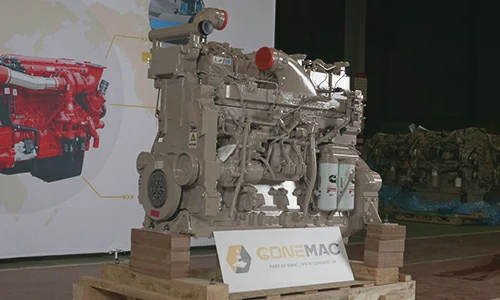
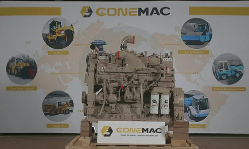
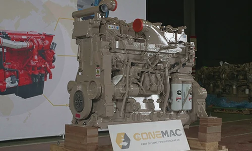
QSK19-G3 Pump Engine
CCEC QSK19-G3 (1800 RPM) Pump Engine is 6-cylinder inline, 19 liters four-strokes engine with 159 mm (6.25 in) bore and 159 mm (6.25 in) stroke.
QSK19-G3 Pump Engine equipped with PT Fuel System, comes with Turbocharged and Air to Air Aftercooled. The standby power at 1800 RPM of CCEC QSK19-G3 Pump engine is 897 HP (669 kW).The prime power at 1800 RPM of CCEC QSK19-G3 Pump engine is 815 HP (608 kW).
As part of EMAC, ConeMac provides pump power pack solution that integrated with air intake, air exhaust, cooling system, control system, transmission and hydraulic accessories, We also supplying special products such as explosion proof engine, generator and water pump set, as well as ultra-low temperature condition engine power pack.
We provide full life cycle services for all customers, from design to power system supply, from installation to commissioning, from after-sales service training to spare parts supply, from trouble shooting to overhaul technical support.
Advantages of CCEC QSK19-G3 Pump Engine
-
Advanced design and sophisticated manufacturing to adapt to various harsh working conditions! High-strength parts, strong ability to work under heavy loads.
-
Cylinder block and cylinder head adopt integrated design. The occurrence of engine water leakage and oil leakage is prevented, and the parts are about 40 % less than other similar engines. The failure rate is greatly reduced.
-
Using forged steel camshaft and crankshaft, high-strength cylinder block design, multiple parts cast on the cylinder block, high rigidity, high pressure resistance, good reliability, and longer service life.
-
The cylinder bore adopts a platform mesh honing design. The perfect geometric structure effectively prevents oil leakage, and the use of advanced technology such as new piston ring components and gasket crimping and molding reduces oil loss.
-
The five key systems of the electronically controlled engine are all developed by CCEC, and have been applied and verified in different fields around the world to ensure the excellent economy and reliability of the product.
-
By optimizing the control strategy and combining with the actual operating conditions of the equipment, the fuel economy can be further improved.
Technical Specifications
Basic Introduction of CCEC QSK19-G3 Pump Engine
| Engine Model: | QSK19-G3 |
| Engine Type: | 4-Cycle; In-line; 6-Cylinder Diesel |
| Displacement: | 19.0 L |
| Rated Speed: | 1800 RPM |
| Rated Power / Speed: | 608 kW @ 1800 RPM |
| Aspiration Method: | Turbocharged and Air to Air Aftercooled |
| Emission Standard: | U.S. EPA Tier 2, CARB Tier 2 |
| Bore * Stroke: | 159 mm * 159 mm |
| Packing Size (L * W * H): | 1679 mm * 872 mm * 1616 mm |
| Weight , Net Dry: | 1900 kg |
| Lead Time: | 15-30 Working Days |
| Payment Terms: | T/T ,L/C |

Engine Model |
Advertised power |
Peak Torque |
Curve & Datasheet |
Compression Ratio |
Fuel System |
| QSK19-P506 | 377 kW @ 1800 RPM | 2755 N.m (2032 lb-ft) @ 1300 RPM | FR-4550 | 15.8 : 1 | MCRS |
| QSK19-P525 | 391 kW @ 2000 RPM | 1775 lb-ft (2407 N.m) @ 1500 RPM | FR-4566 | 15.8 : 1 | N / A |
| QSK19-P560A | 418 kW @ 2000 RPM | 1950 lb-ft (2644 N.m) @ 1500 RPM | FR-4522 | 15.8 : 1 | MCRS |
| QSK19-P560B | 418 kW @ 2000 RPM | 1775 lb-ft (2407 N.m) @ 1500 RPM | FR-4567 | 15.8 : 1 | N / A |
| QSK19-P600 | 447 kW @ 2000 RPM | 1950 lb-ft (2643 N.m) @ 1500 RPM | FR-4565 | 15.8 : 1 | N / A |
| QSK19-P675 | 503 kW @ 1800 RPM | 2200 lb-ft (2983 N.m) @ 1500 RPM | FR-4510 | 15.8 : 1 | N / A |
| QSK19-P700A | 522 kW @ 2000 RPM | 2200 lb-ft (2983 N.m) @ 1500 RPM | FR-4556 | 15.8 : 1 | MCRS |
| QSK19-P700B | 522 kW @ 1800 RPM | 2199 lb-ft (2981 N.m) @ 1500 RPM | FR-4564 | 16 | MCRS |
| QSK19-P760 | 567 kW @ 2100 RPM | 2275 lb-ft (3084 N.m) @ 1500 RPM | FR-4549 | 15.0 : 1 | MCRS |
| QSK19-P800 | 597 kW @ 2100 RPM | 2276 lb-ft (3086 N.m) @ 1500 RPM | FR-4551 | 15.0 : 1 | MCRS |
| ——END—— | |||||
General Information of CCEC QSK19-G3 Pump Engine |
|||
| Engine Model | QSK19-G3 | Standby Power | 897 HP @ 1800 RPM |
| Maxi. Rating | 608 kW @ 1800 RPM | Emission Standard | U.S. EPA Tier 2, CARB Tier 2 |
| Curve & Datasheet | FR-4446 | Peak Torque | N/A |
| Compression Ratio | 15.0 : 1 | Displacement | 19.0 L |
| Type | 4-Cycle; In-line; 6-Cylinder Diesel | Bore * Stroke | 159 mm × 159 mm |
| Fuel System | CMI MCRS | Dry Weight (Fan Hub to Flywheel Engine) | 1900 kg |
| Aspiration | Turbocharged and Air to Air Aftercooled | Wet Weight (Fan Hub to Flywheel Engine) | 1972 kg |
| Minimum Low Idle Speed | 700 RPM | Maximum Low Idle Speed | 900 RPM |
| Configuration | D193103GX03 | Packing Size (L * W * H) | 1679 mm * 872 mm * 1616 mm |
| CPL Code Revision | 1485 | Firing Order | 1-5-3-6-2-4 |
| ——END—— | |||
Engine Performance Data CCEC QSK19-G3 Pump Engine |
||||
| STANDBY | PRIME POWER | |||
| 60 Hz | 50 Hz | 60 Hz | 50 Hz | |
| Governed Engine Speed | 1800 RPM | 1500 RPM | 1800 RPM | 1500 RPM |
| Engine Idle Speed | 700 – 900 RPM | 700 – 900 RPM | 700 – 900 RPM | 700 – 900 RPM |
| Gross Engine Power Output | 669 kW | 634 kW | 608 kW | 574 kW |
| Brake Mean Effective Pressure | 2365 kPa | 2682 kPa | 2150 kPa | 2434 kPa |
| Piston Speed | 9.5 m/s | 7.9 m/s | 9.5 m/s | 7.9 m/s |
| Friction Horsepower | 59 kW | 43 kW | 59 kW | 43 kW |
| Engine Water Flow – 3.0 psi Friction Head | 12.4 L/s | 10.2 L/s | 12.4 L/s | 10.2 L/s |
| Engine Water Flow – Maximum Friction Head | 11 L/s | 9.1 L/s | 11 L/s | 9.1 L/s |
| Intake Air Flow | 975 L/s | 810 L/s | 930 L/s | 775 L/s |
| Exhaust Gas Temperature | 485 ℃ | 515 ℃ | 460 ℃ | 505 ℃ |
| Exhaust Gas Flow | 2365 L/s | 2090 L/s | 2195 L/s | 1975 L/s |
| Air to Fuel Ratio (air : fuel) | 27.3 : 1 | 24.6 : 1 | 28.9 : 1 | 25.5 : 1 |
| Radiated Heat to Ambient | 70 kW | 65 kW | 65 kW | 60 kW |
| Heat Rejection to Jacket Coolant | 250 kW | 230 kW | 225 kW | 215 kW |
| Heat Rejection to Exhaust | 545 kW | 460 kW | 485 kW | 450 kW |
| Heat Rejected to Fuel | 6 kW | 5 kW | 6 kW | 5 kW |
| Heat Rejected to Aftercooler | 205 kW | 165 kW | 185 kW | 150 kW |
| Charge Air Flow | 67 kg/min | 55 kg/min | 64 kg/min | 52 kg/min |
| Turbocharger Compressor Outlet Pressure | 325 kPa | 298 kPa | 301 kPa | 278 kPa |
| Maximum Expected Compressor Outlet Temperature | 236 ℃ | 230 ℃ | 223 ℃ | 219 ℃ |
| ——END—— | ||||
System Technical Data of CCEC QSK19-G3 Pump Engine |
||
| Exhaust System | Maximum Back Pressure – 1500/1800 RPM | 7.8/10.2 kPa |
| Intake Air System | Maximum Intake Air Restriction – with Dirty Filter Element | 635 mm H20 |
| Maximum Intake Air Restriction – with Clean Filter Element | 381 mm H20 | |
| Lubrication System | Oil Pressure – Idle Speed | 138 kPa |
| Oil Pressure – Governed Speed | 276 – 414 kPa | |
| Minimum Oil Temperature | 121 ℃ | |
| Oil Capacity with OP 4084 Oil Pan : High – Low | 72 – 64 L | |
| Total System Capacity (Including Combo Filter) | 84.4 L | |
| Cooling System (Jacket Water Circuit Requirements) |
Coolant Capacity — Engine Only | 41.6 L |
| Maximum Static Head of Coolant Above Engine Crank Centerline | 18.3 m | |
| Standard Thermostat (Modulating) Range | 83 – 95 ℃ | |
| Minimum Pressure Cap | 103 kPa | |
| Maximum Top Tank Temperature for Standby / Prime Power | 104/100 ℃ | |
| Maximum Coolant Friction Head External to Engine | 35 kPa | |
| Cooling System (Charge Air Cooler Requirements) |
Maximum Temp. Rise Between Engine Air Intake and Intake Manifold – 1500/1800 rpm | 21/29 ℃ |
| Maximum Air Pressure Drop from Turbo Air outlet to Intake Manifold – 1500/1800 rpm | 10.2/13.5 kPa | |
| Maximum Intake Manifold Temperature @ 77 °F (25 °C) Ambient – 1500/1800 rpm | 46/54 ℃ | |
| Maximum Intake Manifold Temperature for Engine Protection (Warning Threshold) | 82 ℃ | |
| ——END—— | ||
Scopes of Supply of CCEC QSK19-G3 Pump Engine |
||||
| Fuel System | 1. Fuel Transfer Pump | Exhuast System | 1. Exhuast Manifold | |
| 2. High-Pressure Fuel Pump | 2. Turbocharger | |||
| 3. Fuel Filter | 3. Exhuast Elbow | |||
| Air Intake System | 1. Air Intake Manifold | Starting System | 1. Starter Motor | |
| 2. N/A | 2. Starter Rely | |||
| Cooling System | 1. Water Pump | Power Output System | 1. Flywheel | |
| 2. Engine Fan | 2. Standard Flywheel Housing | |||
| 3. Standard Radiator | 3. N/A | |||
| Lubricating System | 1. Oil Pump | Charging System | 1. Charging Alternator | |
| 2. Oil Filter | 2. N/A | |||
| Engine Shut-Down System | 1. Engine Fuel Shut-Off Solenoidr | Engine Mounting System | 1. Engine Mouting Bracket | |
| Engine Auiliary Accessories | 1. Air Compressor | |||
| ——END—— | ||||
Optional Accessories of CCEC QSK19-G3 Pump Engine |
||||
| Air Intake System | 1. Air Intake Pre-Heater | Exhuast System | 1. Muffler & Bellows | |
| 2. Air Intake Shut-Off Valve | 2. Flame Trap | |||
| 3. Air Filter | 3. Spark Arrestor Type Muffler & Bellows | |||
| 4. Air Intake Pre-Filter | 4. Dpf System | |||
| 5. Air Filter Alarm System | 5. N/A | |||
| Fuel System | 1. Coarse Filter | Lubricating System | 1. Oil Pre-Heater. | |
| 2. Fuel Pre-Heater | 2. N/A | |||
| Starting System | 1. Manual Magnetic Dc Contactor | Cooling System | 1. Silent Type Radiator | |
| 2. Dual Ears Flywheel Housing | 2. Plateau Radiator | |||
| 3. Spring Starter Motor | 3. Salt-Spray Resistant Radiator | |||
| 4. Air Starter Motor | 4. Coolant Pre-Heater | |||
| 5. Hydraulic Starter Motor | 5. Jacket Water Heater | |||
| 6. Manual Magnetic Dc Contactor | 6. N/A | |||
| Engine Auiliary Accessories | 1. Hydraulic Oil Pump | Control System | 1. Can Add Engine Monitoring System, Contro System With Wiring Harness. | |
| 2. Air Conditioner Compressor | 2. Can Add Self-Protection System that Integrated with Alarm System. | |||
| Power Output System | 1. Clutch | Engine Mounting System | 1. Shock Absorber Pad | |
| ——END—— | ||||
Committed to Providing Stable and Reliable Premiem Power System for Global Construction Machinery Manufacturer Partners, ConeMac is A Sub-Brand of the EMAC Group that Focuses on Construction Equipment Application.
ConeMac’s Ranges of Products Mainly Inclduing Marine Construction Engines Power Pack, Construction Equipment Gearbox, Gear Reducer, Explosion-Proof Engines, Generator Set and Water Pump Set for Mining, Oil and Gas Field.
For More Information of Our Industrial Power System Products, You Are Welcome to Visit ConeMac Homepage: Conemac.cn
Modifiable Components of CCEC QSK19-G3 Pump Engine
|
||||
| Air Intake System | 1. Installation Position of Air Filter | Charging System | 1. 12 V Charging Alternator for 12 v Electric System | |
| 2. Upgrade to Heavy-Duty Type Air Fitler | 2. Explosion-Proof Charging Alternator | |||
| 3. N/A | 3. Upgrading to Specified Brand and Speicifications of Charging Alternator | |||
| Exhuast System | 1. Water-Cooled Exhuast Manifold | Lubricating System | 1. Oil Pan Position | |
| 2. Water-Cooled Turbocharger | 2. Number of Dipstick | |||
| 3. Can Modify Installation Position and Direction of Turbocharger | 3. Position of Dipstick Can Choose from 6 Positions | |||
| 4. N/A | 4. Can Modify Oil Filter to be Remote Installation | |||
| Engine Shut-Down System | 1. 12 V Solenoid for 12 V Electric System | Starting System | 1. Upgrading to Specified Brand and Speicifications of Starter Motor | |
| 2. Explosion-Proof Solenoid | 2. 12 V Starter Motor for 12 V Electric System | |||
| Fuel System | 1. Upgrade to Fuel Fitler that Integrated with Fuel Transfer Pump and Fuel Pre-Hearter | Engine Auiliary Accessories | 1. All of auxiliary System can Choose Specified Brands and Specifications | |
| 2. N/A | 2. Additional Auxiliary Systems Can be Added for Special Applications | |||
| Cooling System | 1. Can Modify Engine fan Into Blower Fan or Suction Fan | Power Output System | 1. Can Modify Size of Flywheel Housing and Flywheel | |
| 2. Can Modify Central Position of Engine Cooling Fan | 2. Dual-Ear Flywheel Housing (For Twin-Starter System) | |||
| 3. Can Choose Type of Engine Fan From Mechanical Type or Electric Type | 3. Some of Models can Modify Flywheel Housing Into PTO Integrated Type | |||
| 4. N/A | 4. Engine Have Connecting Port of PTOs, That Able to Provide Power Output | |||
| Engine Mounting System | 1. Can Modify Engine Mouting Bracket | |||
| ——END—— | ||||
Note: All Above Data are Just for Reference, All Data Might Change Without Notices or Updates, Please Contact Our Sales Team to Confirm All Details Via WhatsApp or Email.

Engine Sale Manual

Installation Drawing

Installation Manual

Operation Manual

Parts Catalogue

Report & Certifcate
Tags: Pump Engine | QSK19


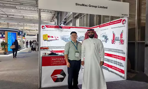
![Deeply Cultivate the International Market, Empowering the Future of Rail ——Focus [PROMotion Expo 2025] SinoMac Exhibition Highlights Review](https://ccec-engine.com/wp-content/uploads/2025/09/Deeply-Cultivate-the-International-Market-Empowering-the-Future-of-Rail-——Focus-PROMotion-Expo-2025-SinoMac-Exhibition-Highlights-Review.webp)