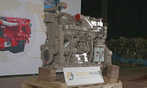
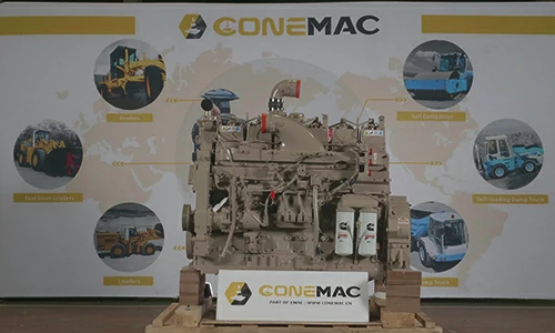
QSK19-P525 Pump Engine
CCEC QSK19-P525 (2000 RPM) Pump Engine is a 6-cylinder inline, 19 liters four-strokes engine with 159 mm (6.25 in) bore and 159 mm (6.25 in) stroke.
QSK19-P525 Pump Engine equipped with CCECModular Common Rail Fuel System, comes with turbocharger and Air-Air intercooler. The Advertised power at 2000 RPM of CCEC QSK19-P525 Pump Engine is 525 HP (391 kW), The maximum torque of the engine at 1500 RPM is 2407 N.m.
As part of EMAC, ConeMac provides pump power pack solution that integrated with air intake, air exhaust, cooling system, control system, transmission and hydraulic accessories, We also supplying special products such as explosion proof engine, generator and water pump set, as well as ultra-low temperature condition engine power pack.
We provide full life cycle services for all customers, from design to power system supply, from installation to commissioning, from after-sales service training to spare parts supply, from trouble shooting to overhaul technical support.
Advantages of CCEC QSK19-P525 Pump Engine
-
Lower oil consumption, Extended stroke, the expansion of the combustion gas more fully, Increase effective efficiency output, the economy is better.
-
Strong power, advanced 4 air valves structure, greater horsepower, air burning more thoroughly, while making low speed torque increase, quicken response speedily, climb strongly.
-
Excellent reliability, with compulsive cold cut articulated pistons, Can bear extreme high mechanical load and heat load, Strength can be comparable with heavy engine.
-
Better emissions, Decorate injector and symmetrical combustion chamber in center, make the cylinder is more homogeneous mixture, burning more fully, lower emissions.
-
Super life, 30 % engines 800,000 km without overhaul.
-
Excellence power, Clean burning, use the advanced lean-burn closed loop electronic control system.
-
Excellent cold start performance, equipped with air suction electric preheater and 7.8 kW power starter, completely improve the cold start performance of the engine. Through the arctic village-MoHe of China -36 °C extreme low temperature validation.
Technical Specifications
Basic Introduction of CCEC QSK19-P525 Pump Engine
| Engine Model: | QSK19-P525 |
| Engine Type: | 4 Cycle In-line 6 Cylinder |
| Displacement: | 19 L |
| Rated Speed: | 2100 RPM |
| Rated Power / Speed: | 391 kW @ 2000 RPM |
| Aspiration Method: | Turbocharged & Air-Air Intercooler |
| Emission Standard: | U.S. EPA Tier 2, CARB Tier 2 |
| Bore * Stroke: | 158.75 mm * 158.75 mm |
| Packing Size (L * W * H): | 2857 mm * 1415 mm * 1766 mm |
| Wet Weight: | 2072 kg |
| Lead Time: | 15-30 Working Days |
| Payment Terms: | T/T ,L/C |

Engine Model |
Advertised power |
Peak Torque |
Curve & Datasheet |
Compression Ratio |
Fuel System |
| QSK19-P506 | 377 kW @ 1800 RPM | 2755 N.m (2032 lb-ft) @ 1300 RPM | FR-4550 | 15.8 : 1 | MCRS |
| QSK19-P525 | 391 kW @ 2000 RPM | 1775 lb-ft (2407 N.m) @ 1500 RPM | FR-4566 | 15.8 : 1 | N / A |
| QSK19-P560A | 418 kW @ 2000 RPM | 1950 lb-ft (2644 N.m) @ 1500 RPM | FR-4522 | 15.8 : 1 | MCRS |
| QSK19-P560B | 418 kW @ 2000 RPM | 1775 lb-ft (2407 N.m) @ 1500 RPM | FR-4567 | 15.8 : 1 | N / A |
| QSK19-P600 | 447 kW @ 2000 RPM | 1950 lb-ft (2643 N.m) @ 1500 RPM | FR-4565 | 15.8 : 1 | N / A |
| QSK19-P675 | 503 kW @ 1800 RPM | 2200 lb-ft (2983 N.m) @ 1500 RPM | FR-4510 | 15.8 : 1 | N / A |
| QSK19-P700A | 522 kW @ 2000 RPM | 2200 lb-ft (2983 N.m) @ 1500 RPM | FR-4556 | 15.8 : 1 | MCRS |
| QSK19-P700B | 522 kW @ 1800 RPM | 2199 lb-ft (2981 N.m) @ 1500 RPM | FR-4564 | 16 | MCRS |
| QSK19-P760 | 567 kW @ 2100 RPM | 2275 lb-ft (3084 N.m) @ 1500 RPM | FR-4549 | 15.0 : 1 | MCRS |
| QSK19-P800 | 597 kW @ 2100 RPM | 2276 lb-ft (3086 N.m) @ 1500 RPM | FR-4551 | 15.0 : 1 | MCRS |
| ——END—— | |||||
General Information of CCEC QSK19-P525 Pump Engine |
|||
| Engine Model | QSK19-P525 | Emission Certification | N / A |
| Advertised Power | 525 HP (391 kW) @ 2000 RPM | Peak Torque | 1775 lb-ft (2407 N-m) @ 1500 RPM |
| Curve & DatAsheet | FR-4566 | Governed Power | N / A |
| Compression Ratio | 15.8 : 1 | Packing Size (L * W * H) | 2857 mm * 1415 mm * 1766 mm |
| Type | 4 Cycle In-line 6 Cylinder | Displacement | 1159 in³ (19.0 L) |
| Fuel System | N / A | Bore * Stroke | 6.25 in * 6.25 in / 158.75 mm * 158.75 mm |
| Aspiration | Turbocharged & Air-Air Intercooler | Minimum Low Idle Speed | 600 RPM |
| Configuration | D193101CX03 | Maximum Low Idle Speed | 1200 RPM |
| CPL Code | 3798 | ||
Engine Sound Pressure Levels3 (Noise) Data of CCEC QSK19-C525 Industrial Engine |
|||
| Top Side | 96.6 dBa | Right Side | 102.2 dBa |
| Left Side | 100.0 dBa | Front Side | 102.1 dBa |
| Exhaust Moise with Aftertreatment | 122.2 dBa | ||
General Engine Data of CCEC QSK19-C525 Industrial Engine |
|||
| Approximate Engine Weight (Wet)⁴ | 4569 lbm / 2072 kg | Maximum Overspeed Capability | 2400 RPM |
| Maximum Installed Engine Power Angle | 6 ° | Maximum Installed Engine Tilt Angle | 6 ° |
| MAss Moment of Inertia of Rotating Components (Excluding Flywheel) | 16.07 in-lbf-sec² / 1.82 kg-m2 | Approximate Engine Weight (dry)⁴ | N / A |
Engine Mounting Data of CCEC QSK19-C525 Industrial Engine |
|||
| Moment of Inertia — X-Axis (Roll) | 1447 in-lbf-sec² / 163.4 kg-m2 | Moment of Inertia — Y-Axis (Pitch) | 3844 in-lbf-sec² / 434.3 kg-m2 |
| Moment of Inertia — Z-Axis (Yaw) | 3041 in-lbf-sec² / 343.6 kg-m2 | Center of Gravity — From Rear Face of Block | 23.55 in / 598 mm |
| Maximum Crankshaft Thrust Bearing Load Limit — Intermittent Load | 1500 lbf / 6672 N | Maximum Bending Moment Available From Front of Crankshaft — 270 Degrees | 440 lb-ft / 597 N.m |
| Maximum Static Bending Moment at Rear Face of Block | 2730 lb-ft / 3702 N.m | Maximum Crankshaft Thrust Bearing Load Limit — Continuous Load | 750 lbf / 3336 N |
| Center of Gravity — From Engine Centerline to Left Side of Engine (as Viewed From Rear of Engine) | N / A | Maximum Bending Moment Available From Front of Crankshaft — 0 Degrees | 440 lb-ft / 597 N.m |
| Maximum Bending Moment Available From Front of Crankshaft — 90 Degrees | 440 lb-ft / 597 N.m | Maximum Bending Moment Available From Front of Crankshaft — 180 Degrees | 440 lb-ft / 597 N.m |
| Center of Gravity — Above Crankshaft Centerline | 11.10 in / 282 mm | ||
High Temperature Circuit (HTC) of CCEC QSK19-C525 Industrial Engine |
|||
| HTC Coolant Volume (Engine Only) | 44 quarts / 42 L | Maximum External HTC Restriction | 5 PSI / 34.5 kPa |
| HTC Thermostat Opening Temperature | 180 °F / 82 °C | Maximum Auxiliary Coolant Flow at 2000 Rpm | N / A |
| Maximum HTC Thermostat Outlet Temperature at Lat (Maximum Top Tank Temperature) | 212 °F / 100 °C | Minimum Operating HTC Temperature (For Continuous Cold Weather Applications) | 160 °F / 71 °C |
| HTC Thermostat Fully Open Temperature | 202 °F / 94 °C | ||
| ——END—— | |||
Performance Data of CCEC QSK19-P525 Pump Engine |
|||||||||
| Advertised Power | Peak Torque | Advertised Power | Peak Torque | ||||||
| Engine Speed | 2,000 RPM | 1,500 RPM | Inlet Air Flow | 1,460 ft>³/min | 689 L/s | 1,200 ft>³/min | 566 L/s | ||
| Power Output | 525 HP | 391 kW | 507 HP | 378 kW | Charge Air Flow | 105 lb/min | 48 kg/min | 85 lb/min | 39 kg/min |
| Torque Output | 1,379 lb-ft | 1,870 N.m | 1,775 lb-ft | 2,407 N.m | Exhaust Gas Flow | 3,450 ft>³/min | 1,628 L/s | 3,200 ft>³/min | 1,510 L/s |
| Friction Horsepower | 95 HP | 71 kW | 57 HP | 43 kW | Exhaust Gas Temperature | 895 °F | 479 ℃ | 1,042 °F | 561 ℃ |
| Intake Manifold Pressure | 45 in-Hg | 152 kPa | 47 in-Hg | 159 kPa | Heat Rejection to Ambien Air | 2,180 BTU/min | 38 kW | 2,050 BTU/min | 36 kW |
| Turbo Comp. Outlet Pressure | 49 in-Hg | 165 kPa | 49 in-Hg | 165 kPa | Heat Rejection to Exhaust Gas | 22,930 BTU/min | 403 kW | 21,200 BTU/min | 373 kW |
| Turbo Comp. Outlet Temperature | 320 °F | 160 ℃ | 328 °F | 164 ℃ | Heat Rejection to HTC Coolant | 9,316 BTU/min | 164 kW | 9,290 BTU/min | 163 kW |
| ——END—— | |||||||||
System Technical Data of CCEC QSK19-P525 Pump Engine |
||
| Intake Air System | Maximum Intake Air Restriction with-Clean Filter | 15 in-H2O / 3.7 kPa |
| Maximum Intake Air Restriction with-Dirty Filter | 25 in-H2O / 6.2 kPa | |
| Minimum Air Cleaner Dirt Holding Capacity | 25 g / cfm | |
| Maximum Intake Air Bleed for Accessories at Intake Manifold (Not Including Air Compressor) | N / A | |
| Recommended Intake Piping Size (Inner Diameter) | 5.8 in / 147 mm | |
| Exhaust System | Maximum Exhaust Restriction | 3 in-Hg / 10 kPa |
| Recommended Exhaust Piping Size (Inner Diameter) | 8.00 in / 203 mm | |
| Maximum Static Bending Moment at Exhaust Outlet Flange | 20 lb-ft / 27 N.m | |
| Lubrication System | Nominal Operating Oil Pressure at -Minimum Low Idle Speed | 20 PSI / 138 kPa |
| Nominal Operating Oil Pressure at -Advertised Speed | 70 PSI / 483 kPa | |
| Minimum Oil Pressure Within 4 Seconds of Engine First Firing at Minimum Low Idle Speed (MeAsured at Urbocharger Oil Inlet) | 17 PSI / 117 kPa | |
| Maximum Oil Flow to All Accessories | 5 gpm / 18.93 L/min | |
| Maximum Oil Pressure Spike on Cold Engine | 150 PSI / 1034 kPa | |
| Fuel System | Maximum Heat Rejection to Return Fuel Which Occurs at The Following Conditions | 183 BTU/min / 3 kW |
| Maximum Heat Rejection to Return Fuel Which Occurs at The Following Conditions-Fuel Return Flow | 606 lb/hr / 275 kg/hr | |
| Maximum Heat Rejection to Return Fuel Which Occurs at The Following Conditions-Fuel Return Temperature (Prior to Fuel Cooler) | 160 °F / 71 °C | |
| Maximum Fuel Supply Flow | 805 lb/hr / 365 kg/hr | |
| Maximum Fuel Return Flow | 606 lb/hr / 275 kg/hr | |
| Maximum Fuel Supply Temperature (MeAsured at On-Engine Fuel Inlet Fitting) | 160 °F / 71 °C | |
| Maximum Fuel Supply Pressure (MeAsured at On-Engine Fuel Inlet Fitting) | N / A | |
| Maximum Fuel Return Restriction (MeAsured at On-Engine Fuel Drain Fitting) | 21 in-Hg / 71 kPa | |
| Fuel System-Stage 1 filter(s) | Maximum Combined Fuel Supply Restriction of Stage 1 Assembly & Oem Plumbing (MeAsured at On-Engine Fuel Inlet Fitting) with-Clean Stage 1 Fuel Filter(S) at Maximum Fuel Supply Flow | 5 in-Hg / 16.9 kPa |
| Maximum Combined Fuel Supply Restriction of Stage 1 Assembly & Oem Plumbing (MeAsured at On-Engine Fuel Inlet Fitting) with-Dirty Stage 1 Fuel Filter(S) at Maximum Fuel Supply Flow | 10 in-Hg / 34.0 kPa | |
| Nominal Restriction of Clean Stage 1 Fuel Filter Assembly at Maximum Fuel Supply Flow | 1 in-Hg / 4.0 kPa | |
| Maximum Fuel Inlet Pressure MeAsured at Stage 1 Inlet | 5 PSI / 34.0 kPa | |
| Recommended Maximum Fuel Inlet Pressure for Seeing Is Believing® (MeAsured at Stage 1 Inlet) | 1 PSI / 4.0 kPa | |
| Cooling Systems | Cooling System Type | 1 Pump-1 Loop |
| Minimum Fill Rate | 5 gpm / 19 L / min | |
| Maximum Deaeration Time | 25 min | |
| Acceptable Types of Deaeration Systems | Fully Deaerating | |
| Minimum Water Pump Inlet Pressure with Fully Deaerating Cooling System | N / A | |
| Maximum Static Head of Coolant Above Crankshaft Centerline | 60 ft / 18.3 m | |
| Minimum Pressure Cap Rating at Sea Level | 7 PSI / 48 kPa | |
| Maximum Pressure Cap Rating at Sea Level | 15 PSI / 103 kPa | |
| Minimum Coolant Expansion Space (% of Total Cooling System Capacity) | 5 % | |
| Minimum Drawdown (% of Total Cooling System Capacity) | 11 % | |
| Charge-Air Cooling (CAC) System | Maximum Intake Manifold Temperature at 77 °F (25 °C) Ambient Air Temperature | 120 °F / 49 °C |
| Maximum Pressure Drop Across Charge-Air Cooler And Oem Cac Piping (Impd) | 4 in-Hg / 14 kPa | |
| Maximum Intake Manifold Temperature Differential (Ambient to Imt) (Imtd) | 43 delta °F / 23.9 delta °C | |
| Electrical System | System Voltage | 24 V |
| Minimum Battery Capacity for Engine Only [Cold Soak at 0 °F (- 18 °C) Or Above]-Cold Cranking Amperes (Cca) | 900 CCA | |
| Minimum Battery Capacity for Engine Only [Cold Soak at 0 °F (- 18 °C) Or Above]-Reserve Capacity (Rc) | 320 min | |
| Cranking System | Minimum Cranking Speed | 150 RPM |
| Maximum Parasitic Load 10 °F (- 12 °C) | N / A | |
| Unaided Cold Start-Minimum Ambient Temperature | 10 °F / -12.2 °C | |
| Unaided Cold Start-Cranking Torque at Minimum Unaided Cold Start Temperature | 1302 lb-ft / 1765 N.m | |
| Aided Cold Start-Minimum Ambient Temperature with Only Ether | – 5 °F /-21 °C | |
| Aided Cold Start -Minimum Ambient Temperature with Only Coolant And Oil Heaters | – 5 °F /-21 °C | |
| ——END—— | ||
Scopes of Supply of CCEC QSK19-P525 Pump Engine |
||||
| Air Intake System | 1. Air Intake Manifold | Exhuast System | 1. Exhuast Manifold | |
| 2. Water-air Intercooler | 2. Turbocharger | |||
| 3. N/A | 3. Exhuast Elbow | |||
| Fuel System | 1. Fuel transfer pump | Starting System | 1. Starter motor | |
| 2. High-pressure fuel pump | 2. Starter rely | |||
| 3. Fuel Filter | 3. N/A | |||
| Charging System | 1. Charging alternator | Engine Shut-Down System | 1. Engine fuel shut-off solenoid | |
| Lubricating System | 1. Oil pump | Cooling System | 1. Water pump | |
| 2. Oil filter | 2. Engine Fan | |||
| 3. N/A | 3. Standard radiator | |||
| Power Output System | 1. Flywheel | Engine Mounting System | 1. Engine Mouting Bracket | |
| 2. Standard flywheel housing | 2. N/A | |||
| Engine Auiliary Accessories | 1. Air compressor | |||
| 2. Power steering pump | ||||
| ——END—— | ||||
Optional Accessories of CCEC QSK19-P525 Pump Engine |
||||
| Air Intake System | 1. Air Intake pre-heater | Exhuast System | 1. Muffler & bellows | |
| 2. Air intake shut-off valve | 2. Flame trap | |||
| 3. Air filter | 3. Spark arrestor type Muffler & bellows | |||
| 4. Air intake pre-filter | 4. DPF system | |||
| 5. Air filter alarm system | 5. N/A | |||
| Fuel System | 1. Coarse Filter | Starting System | 1.Manual Magnetic DC Contactor | |
| 2. Fuel pre-heater | 2. Dual ears flywheel housing | |||
| 3. N/A | 3. Spring Starter Motor | |||
| 4. N/A | 4. Air Starter Motor | |||
| 5. N/A | 5. Hydraulic Starter Motor | |||
| Lubricating System | 1. Oil pre-heater. | Cooling System | 1. Silent Type Radiator | |
| 2. N/A | 2. Plateau Radiator | |||
| 3. N/A | 3. Salt-Spray Resistant Radiator | |||
| 4. N/A | 4. Coolant pre-heater | |||
| Power Output System | 1. Clutch | Engine Mounting System | 1. Shock absorber pad | |
| Engine Auiliary Accessories | 1. Hydraulic oil pump | Control System | 1. Can add mechanical accelerator pedal | |
| 2. Air conditioner compressor | 2. N/A | |||
| 3. N/A | 3. N/A | |||
| ——END—— | ||||
As part of EMAC, PumpMac focusing on water pump set related business, from pump drive engine, to WPT PTO, from complete engine power pack to complete water pump set, from NFPA20 standard fire fighting pump accessories to fire pump drive package, from explosion proof accessories to complete explosion-proof water pump set, PumpMac provides professional one-stop solution for everything customer needed for water pump set industry.
For more information of our pump drive power pack and complete water pump set products, you are welcome to visit PumpMac homepage: www.pumpmac.com
Modifiable Components of CCEC QSK19-P525 Pump Engine |
||||
| Air Intake System | 1. Installation position of air filter | Exhuast System | 1. Can modify installation position and direction of | |
| 2. Upgrade to heavy-duty type air fitler | turbocharger | |||
| 3. N/A | 2. Water-cooled exhuast manifold | |||
| 4. N/A | 3. Water-cooled turbocharger | |||
| Fuel System | 1. Upgrade to fuel fitler that integrated with fuel transfer | Starting System | 1. 12 V starter motor for 12 v electric system | |
| pump and fuel pre-hearter | 2. Upgrading to specified brand and speicifications of | |||
| 2. N/A | starter motor | |||
| Charging System | 1. 12 V charging alternator for 12 v electric system | Engine Shut-Down System | 1. 12 V solenoid for 12 v electric system | |
| 2. Explosion-proof charging alternator | 2. Explosion-proof solenoid | |||
| 3. Upgrading to specified brand and speicifications of | 3. N/A | |||
| charging alternator | 4. N/A | |||
| Lubricating System | 1. Oil Pan position | Cooling System | 1. Can modify engine fan into blower fan or suction fan | |
| 2. Number of dipstick | 2. Can modify central position of engine cooling fan | |||
| 3. Position of dipstick can choose from 6 positions | 3. Can choose type of engine fan from mechanical type or | |||
| 4. Can modify oil filter to be remote installation | electric type | |||
| Power Output System | 1. Can modify size of flywheel housing and flywheel. | Engine Mounting System | 1. Can modify engine mouting bracket. | |
| 2. Dual-ear flywheel housing (For twin-starter system) | 2. N/A | |||
| 3. Some of models can modify flywheel housing into PTO | 3. N/A | |||
| integrated type. | 4. N/A | |||
| 4. Engine have connecting port of PTOs, that able to | 5. N/A | |||
| provide power output. | 6. N/A | |||
| Engine Auiliary Accessories | 1. All of auxiliary system can choose specified brands and | |||
| specifications. | ||||
| 2. Additional auxiliary systems can be added for special | ||||
| applications. | ||||
| ——END—— | ||||
Note: All Above Data are Just for Reference, All Data Might Change Without Notices or Updates, Please Contact Our Sales Team to Confirm All Details Via WhatsApp or Email.

Engine Sale Manual

Installation Drawing

Installation Manual

Operation Manual

Parts Catalogue

Report & Certifcate
Tags: Pump Engine | QSK19


![Deeply Cultivate the International Market, Empowering the Future of Rail ——Focus [PROMotion Expo 2025] SinoMac Exhibition Highlights Review](https://ccec-engine.com/wp-content/uploads/2025/09/Deeply-Cultivate-the-International-Market-Empowering-the-Future-of-Rail-——Focus-PROMotion-Expo-2025-SinoMac-Exhibition-Highlights-Review.webp)