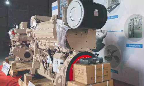
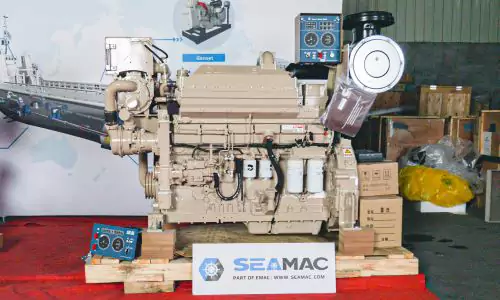
K19-M550 Marine Engine
CCEC K19-M550 (2100 RPM) Marine Main Engine is a 6-cylinder inline, 19 liters four-strokes engine with 159 mm (6.25 in) bore and 159 mm (6.25 in) stroke.
K19-M550 Marine Main Engine equipped with PT Fuel System, comes with turbocharger and Water-Air intercooler, this marine diesel engine complies with IMO-NOx requirements of the International Maritime Organization (IMO). The continuous power at 2100 RPM of CCEC K19-M550 Marine Main Engine is 550 HP (410 kW). The maximum torque of the engine at 1500 RPM is 2052 N.m.
Based on standard CCEC marine main engines, SeaMac provides both heat exchanger cooling and keel cooling marine main engines, we also provide complete propulsion system that including marine engine, gearbox, shaft, propeller as complete power system.
SeaMac provides full life cycle services for all our customers, from design to power system supply, from installation to commissioning, from after-sales service training to spare parts supply, from trouble shooting to overhaul technical support.
All of CCEC marine main engine are comes with dry type exhaust system, which means dry type exhaust manifold and dry type turbocharger, SeaMac provides upgrading services for water-cooled exhaust system, which modify dry type exhaust system into water-cooled exhaust system, which are quite important and often requested by passenger boat projects.
Advantages of K19-M550 Marine Engine
-
The cylinder block and cylinder head adopt integrated design, which prevents the occurrence of water leakage and oil leakage, and greatly reduces the failure rate. The application of strengthened cylinder liners and chrome-plated piston rings improves the durability of the engine and prolongs the life of the engine.
-
It meets the requirements of China Inland River 1, China Inland River 2, and IMO TIER2 stage emission regulations, and adopts CMI’ BHT3B supercharger optimized for marine engines. emissions while enhancing engine reliability.
-
With high injection pressure, overspeed protection, low-pressure fuel supply, fewer pipelines, and low failure rate, it can ensure full fuel combustion and achieve high-efficiency energy-saving effects. The equipped ESTC electronic oil timing control valve can accurately supplement and adjust the timing and improve the combustion smoke color at low idle speed.
-
The design of the exhaust system of Chongqing CMI marine engine is reasonable, and the water-cooled supercharger and water-cooled exhaust pipe can better reduce the surface temperature of the engine and meet the requirements of SOLAS safety regulations.
Technical Specifications
Basic Introduction of CCEC K19 – M550 Marine Main Engine
| Engine Model: | K19 – M550 |
| Engine Type: | 6 Cylinders, in Line |
| Displacement: | 19 L |
| Rated Power / Speed: | 550 HP @ 2100 RPM |
| Aspiration Method: | Turbocharged & Water – Air Intercooler |
| Emission Standard: | Euro II |
| Bore * Stroke: | 159 mm * 159 mm |
| Packing Size (L * W * H): | 1573 mm * 796 mm * 1343 mm |
| Dry Weight: | 2073 kg |
| Lead Time: | 15-30 Working Days |
| Payment Terms: | T / T ,L / C |


Engine Model |
Advertised Power |
Aspiration |
Compression Ratio |
Fuel System |
| K19 – M500 | 373 kW (500 HP) @ 1800 RPM | Turbocharged & Water – Air Intercooler | 14.5 : 1 | PT |
| K19 – M550 | 410 kW (550 HP) @ 2100 RPM | Turbocharged & Water – Air Intercooler | 14.5 : 1 | PT |
| K19 – M600 | 447 kW (600 HP) @ 1800 RPM | Turbocharged & Water – Air Intercooler | 14.5 : 1 | PT |
| K19 – M640 | 477 kW (640 HP) @ 1800 RPM | Turbocharged & Water – Air Intercooler | 14.5 : 1 | PT |
| KT19 – M425 | 317 kW (425 HP) @ 1800 RPM | Turbocharged | 15.5 : 1 | PT |
| KTA19 – M470 | 351 kW (470 HP) @ 1800 RPM | Turbocharged & Water – Air Intercooler | 15.5 : 1 | PT |
| KTA19 – M500 | 373 kW (500 HP) @ 1800 RPM | Turbocharged & Water – Air Intercooler | 15.5 : 1 | PT |
| KTA19 – M550 | 410 kW (550 HP) @ 2100 RPM | Turbocharged & Water – Air Intercooler | 15.5 : 1 | PT |
| KTA19 – M3 – 500 | 373 kW (500 HP) @ 1800 RPM | Turbocharged & Water – Air Intercooler | 13.8 : 1 | PT |
| KTA19 – M3 – 600 | 447 kW (600 HP) @ 1800 RPM | Turbocharged & Water – Air Intercooler | 13.8 : 1 | PT |
| KTA19 – M3 – 640 | 477 kW (640 HP) @ 1800 RPM | Turbocharged & Water – Air Intercooler | 13.8 : 1 | PT |
| KTA19 – M4 – 700 | 522 kW (700 HP) @ 2100 RPM | Turbocharged & Water – Air Intercooler | 13.8 : 1 | PT |
| ——END—— | ||||
| General Information of CCEC KTA19 – M550 Marine Main Engine | |||
| Engine Model | KTA19 – M550 | Configuration | D193080MX02 |
| Curve No. | M – 488 | CPL Code | CQ415 |
| Displacement | 1150 in3 / 19 L | Bore * Stroke | 159 mm * 159 mm / 6.25 in * 6.25 in |
| Fuel System | PT | Cylinders | 6, in Line |
| Advertised Power | 410 kW (550 HP) @ 2100 RPM | Aspiration | Turbocharged & Water – Air Intercooler |
| Rating Type | Medium Continuous | Peak Engine Torque @ 1500 RPM | 1513 lb.ft / 2052 N.m |
| Brake Mean Effective Pressure | 179 PSI / 1233 kPa | Minimum Idle Speed Setting | 625 – 675 RPM |
| Normal Idle Speed Variation | ± 25 RPM | High Idle Speed Range Minimum | 2234 RPM |
| High Idle Speed Range Maximum | 2554 RPM | Compression Ratio | 14.5 : 1 |
| Piston Speed | 2185 ft/min / 11.1 m/sec | Weight (Dry) – Engine Only – Average | 4566 lb. / 2073 kg |
| Weight (Dry) – Engine With Heat Exchanger System – Average | 4958 lb. / 2251 kg | ||
| ——END—— | |||

| System Technical Data of CCEC KTA19 – M550 Marine Main Engine | ||
| Fuel System | Avg. Fuel Consumption – ISO 8178 E3 Standard Test Cycle | 20.2 GAL/hr / 76.4 L/hr |
| Fuel Consumption at Rated Speed | 29.1 GAL/hr / 110 L/hr | |
| Approximate Fuel Flow to Pump | 87 GAL/hr / 330 L/hr | |
| Maximum Allowable Fuel Supply to Pump Temperature | 140 °F / 60 °C | |
| Approximate Fuel Flow Return to Tank Temperature | 126 °F / 52 °C | |
| Fuel Pressure – Pump Out / Rail Mechanical Gauge | 149 PSI / 1027 kPa | |
| Air System | Intake Manifold Pressure | 59 in. Hg / 200 kPa |
| Intake Air Flow | 1563 CFM / 738 L/sec | |
| Heat Rejection to Ambient | 1195 BTU/min / 21 kW | |
| Exhaust System | Exhaust Gas Flow | 3887 CFM / 1835 L/sec |
| Exhaust Gas Temperature (Turbine Out) | 743 °F / 395 °C | |
| Heat Rejection to Exhaust (Manifold) | 1006 °F / 541 °C | |
| Emsission (in accordance with ISO 8178 Cycle E3) | ||
| NOx (Oxides of Nitrogen) | 4.28 g/HP.hr / 5.73 g/kW.hr | |
| Cooling System | Sea Water Pump Specifications | MAB 0.08.17 – 07 / 16 / 2001 |
| Pressure Cap Rating (With Heat Exchanger Option) | 7 PSI / 50 kPa | |
| Engines with Low Temperature Aftercooling (if applicable) – Main Cooler | ||
| Coolant Flow to Engine Heat Exchanger / Keel Cooler | 175 GAL / 664 L/min | |
| Standard Thermostat Operating Range (Start to Open) | 180 °F / 82 °C | |
| Standard Thermostat Operating Range (Full Open) | 203 °F / 95 °C | |
| Heat Rejection to Engine Coolant3 | 11953 BTU/min / 210 kW | |
| Engines with Low Temperature Aftercooling (if applicable) – LTA Cooler | ||
| Coolant Flow to Engine Heat Exchanger / Keel Cooler | 30 GAL / 114 L/min | |
| Standard Thermostat Operating Range (Start to Open) | 156 °F / 69 °C | |
| Standard Thermostat Operating Range (Full Open) | 172 °F / 78 °C | |
| Heat Rejection to Engine Coolant3 | 6603 BTU/min / 116 kW | |
| Maximum Coolant Inlet Temperature from LTA Cooler | 145 °F / 63 °C | |
| ——END—— | ||
Scopes of Supply of CCEC KTA19 – M550 Marine Main Engine |
|||
| Exhaust System | 1. Silencer | Lubricating System | 1. Oil Pump |
| 2. Bellows | 2. Oil Filter | ||
| Fuel System | 1. Fuel Pump | Starting System | 1. Starter Motor |
| 2. Oil Cut Solenoid Valve | 2. Fywheel Housing | ||
| 3. Fuel Filter | 3. Flywheel | ||
| Charging System | 1. Alternator | Control System | 1.Stadnby Control Panel |
| Cooling System | 1. Seawater Pump | ||
| 2. Heat Exchanger | |||
| ——END—— | |||
Optional Accessories of CCEC KTA19 – M550 Marine Main Engine |
|||
| Exhaust System | 1. Silencer | Power System | 1. Battery |
| Fuel System | 1. Float Fuel Tank | Cooling System | 1. Radiator |
| 2. Oil – Water Separator | 2. Cooling Fan | ||
| 3. Manual Fouling Pump | 3. Sea Water Pump | ||
| 4. Fuel Inlet and Outlet Hose | 4. Heat Exchanger | ||
| Remote Control System | 1. Sea Water Pump | ||
| 2. Heat Exchanger | |||
| ——END—— | |||
Committed to providing reliable premium propulsion system and power system for all kinds of ships around the world, SeaMac is a sub-brand of EMAC group that focused on maritime application. SeaMac’s ranges of products mainly inclduing marine main engine, marine gearbox, marine propellers, marine control lever system, marine auxiliary engine, marine generator set and emergency generator set.
For more information of our marine proplusion and power system products, you are welcome to visit SeaMac homepage: www.seamac.com
Modifiable components of CCEC KTA19 – M550 Marine Main Engine
|
||||
| Air Intake System | 1. Installation Position of Air Filter | Starting System | 1. 12 V Starter Motor for 12 V Electric System | |
| 2. Upgrade to Heavy – Duty Type Air Fitler | 2. Upgrading to Specified Brand and Speicifications of Starter Motor | |||
| Exhuast System | 1. Can Modify Installation Position and Direction of Turbocharger | Charging System | 1. 12 V Charging Alternator for 12 V Electric System | |
| 2. Water – Cooled Exhuast Manifold | 2. Explosion – Proof Charging Alternator | |||
| 3. Water – Cooled Turbocharger | 3. Upgrading to Specified Brand and Speicifications of Charging Alternator | |||
| Fuel System | 1. Upgrade to Fuel Fitler That Integrated With Fuel Transfer Pump and Fuel Pre – Hearter | Engine Auiliary Accessories | 1. Additional Auxiliary Systems Can Be Added for Special Applications | |
| Engine Shut-Down System | 1. 12 V Solenoid for 12 V Electric System | Cooling System | 1. Can Modify Engine Into Keel Cooling System | |
| 2. Explosion – Proof Solenoid | ||||
| Lubricating System | 1. Oil Pan Position | Power Output System | 1. Can Modify Size of Flywheel Housing and Flywheel. | |
| 2. Number of Dipstick | 2. Dual – Ear Flywheel Housing (for Twin – Starter System) | |||
| 3. Position of Dipstick Can Choose From 6 Positions | 3. Some of Models Can Modify Flywheel Housing Into Pto Integrated Type | |||
| 4. Can Modify Oil Filter to Be Remote Installation | 4. Engine Have Connecting Port of Ptos, That Able to Provide Power Output | |||
| Engine Mounting System | 1. Can Modify Engine Mouting Bracket | |||
| ——END—— | ||||
Note: All Above Data are Just for Reference, All Data Might Change Without Notices or Updates, Please Contact Our Sales Team to Confirm All Details Via WhatsApp or Email.

Engine Sale Manual

Installation Drawing

Installation Manual

Operation Manual

Parts Catalogue


![Deeply Cultivate the International Market, Empowering the Future of Rail ——Focus [PROMotion Expo 2025] SinoMac Exhibition Highlights Review](https://ccec-engine.com/wp-content/uploads/2025/09/Deeply-Cultivate-the-International-Market-Empowering-the-Future-of-Rail-——Focus-PROMotion-Expo-2025-SinoMac-Exhibition-Highlights-Review.webp)