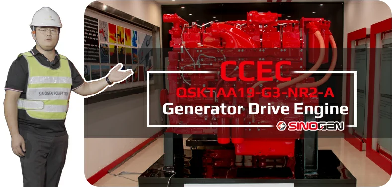
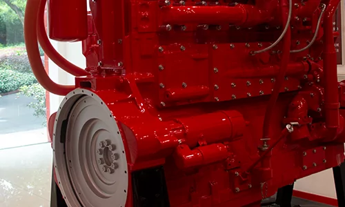
QSKTAA19-G3-NR2-A G-Drive Engine
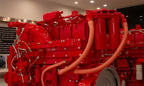
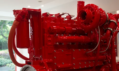
CCEC QSK19-G3-NR2-A (1500 RPM) Generator Drive Engine is 6-Cylinder In-line, 19 liters (1159 in3) Four-Strokes Engine with 159 mm (6.25 in) Bore and 159 mm (6.25 in) Stroke.
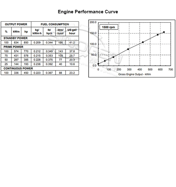
QSK19-G3-NR2-A Generator Drive Engine Equipped with CMI MCRS Fuel System, Comes with Turbocharged and Air to Air Aftercooled.The Standby Power for 50 Hz Generator Set (1500 RPM) of CCEC QSK19-G3-NR2-A Generator Drive Engine is 850 HP (634 kW). The Prime Power for 50 Hz Generator Set (1500 RPM) of CCEC QSK19-G3-NR2-A Generator Drive Engine is 770 HP (574 kW).The Continuous Power for 50 Hz Generator Set (1500 RPM) of CCEC QSK19-G3-NR2-A Generator Drive Engine is 450 HP (336 kW).
As Part of EMAC, SinoGen Also Provide Complete Power Supply Solutions that Powered by CCEC, Our Ranges of Products Including Open Type Generator Set, Silence Type Generator Set, Super Silence Type Generator Set, Mobile Trailer, Complete Power Truck and Complete Power Car for Railways Applications.
We Provide Full Life Cycle Services for All Customers, From Design to Power System Supply, from Installation to Commissioning, from After-Sales Service Training to Spare Parts Supply, From Trouble Shooting to Overhaul Technical Support.
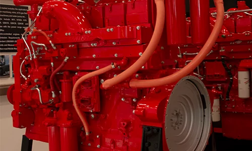
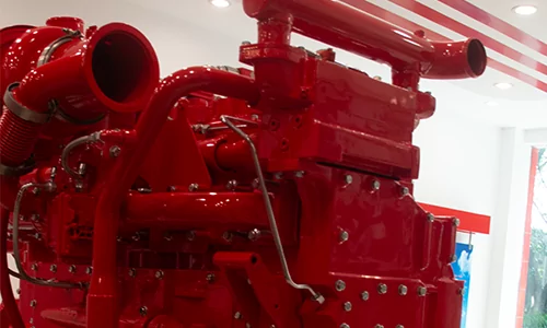
Advantages of QSKTAA19-G3-NR2-A G-Drive Engine
-
High quality alloy cast iron for the rigidity performance and lower vibration and noise. Wet and replaceable cylinder liners for better heat rejection performance and easier replacement.
-
4 valves per cylinder, Optimize the mixed level which lead to an excellent fuel consumption rate and emission performance. High quality alloy cast iron, one cylinder one head, single camshaft and special designed outine for better reliability and durability.
-
CMS unique PT with fixture and Step Timing control for precise fuel injection make the fuel injection pressure above 120 Mpa, which leads to an excellent fuel consumption rate and emission performance. Check valve in fuel tube improve reliability.
-
Gear water pump and great flux channel design provide effective cooling. Spin-in water filter makes the coolant clean and keeps it in normal acidity.
-
Advanced Holset turbocharger and after-cooled technology, pulse exhaust manifold reduce exhaust temperature, provide excellence fuel consumption and emission performance.
Technical Specifications
Basic Introduction of CCEC QSKTAA19-G3-NR2-A G-Drive Engine
| Engine Model: | QSKTAA19-G3 NR2-A (-A means 1500 RPM engine) |
| Engine Type: | 6 – Cylinder; In – line; 4 – Cycle |
| Displacement: | 19 L |
| Rated Power / Speed: | 574 kW @ 1500 RPM |
| Aspiration Method: | TC & Air to Air Aftercooled |
| Emission Standard: | EPA Tier 2 |
| Bore * Stroke: | 159 mm * 159 mm |
| Packing Size (L * W * H): | 1534 mm * 781 mm * 1355 mm |
| Dry Weight: | 1900 kg |
| Lead Time: | 15-30 Working Days |
| Payment Terms: | T / T ,L / C |
Engine Model |
Prime Power |
Aspiration |
Configuration |
Performance Curve |
Compression Ratio |
| QSK19-G3-A | 770 HP (574 kW) at 1500 RPM | Turbocharged & Air – Air Aftercooled | D193103GX03 | FR-4446 | 15.0 : 1 |
| QSK19-G3-B | 815 HP (608 kW) at 1800 RPM | Turbocharged & Air – Air Aftercooled | D193103GX03 | FR-4446 | 15.0 : 1 |
| QSK19-G4-A | 770 HP (574 kW) at 1500 RPM | Turbocharged & Charge Air Cooled | D193103GX03 | FR-4580 | 15.0 : 1 |
| QSK19-G4-B | 750 HP (559 kW) at 1800 RPM | Turbocharged & Charge Air Cooled | D193103GX03 | FR-4580 | 15.0 : 1 |
| QSK19-G5 | 815 HP (608 kW) at 1800 RPM | Turbocharged & Charge Air Cooled | D193103GX03 | FR-4581 | 15.0 : 1 |
| QSK19-G11 | 813 HP (606 kW) at 1500 RPM | Turbocharged & Charge Air Cooler | D193103GX03 | FR-4769 | 15.0 : 1 |
| QSK19-G11X | 894 HP (667 kW) at 1500 RPM | Turbocharged & Air – Air Aftercooled | D193103GX03 | FR-4769 | 15.0 : 1 |
| QSK19-G12 | 675 HP (503 kW) at 1500 RPM | TC & Low Temperature Aftercooled | D193103GX03 | FR-4773 | 15.0 : 1 |
| QSK19-G13 | 605 HP (451 kW) at 1500 RPM | Turbocharged & Charge Air Cooled | D193103GX03 | FR-4773 | 15.8 : 1 |
| QSK19-G14 | 539 HP (402 kW) at 1500 RPM | Turbocharged & Charge Air Cooled | D193103GX03 | FR4791 | 15.8 : 1 |
| QSKTAA19-G3-NR2-A | 770 HP (574 kW) at 1500 RPM | Turbocharged & Air – Air Aftercooled | D193103GX03 | FR-4446 | 15.0 : 1 |
| QSKTAA19-G3-NR2-B | 815 HP (608 kW) at 1800 RPM | Turbocharged & Air – Air Aftercooled | D193103GX03 | FR-4446 | 15.0 : 1 |
| ——END—— | |||||
General Information of CCEC QSKTAA19-G3-NR2-A Generator Engine |
|||
| Engine Model | QSKTAA19-G3-NR2-A | Configuration | D193103GX03 |
| Performance Curve | FR-4446 | CPL | 1485 |
| Type | 4-Cycle; In-line; 6-Cylinder Diesel | Aspiration | Turbocharged and Air to Air Aftercooled |
| Stroke * Bore | 159 mm * 159 mm / 6.25 in * 6.25 in | Displacement | 1159 in3 / 19.0 L |
| Compression Ratio | 15.0 : 1 | Fuel System | CMS MCRS |
| Prime Power & Engine Speed | 770 HP (574 kW) at 1500 RPM | Continuous Power & Engine Speed | 450 HP (336 kW) at 1500 RPM |
| No. of Cylinders | 6 | Emissions | Refer to Emission Data Sheet for Details |
| Standby Power & Engine Speed | 850 HP (634 kW) at 1500 RPM | Fan to Flywhee | 4953720 |
Installation Data of CCEC QSKTAA19-G3-NR2-A Generator Engine |
|||
| Wet Weight – Fan to Flywheel Engine | 4350 lb / 1973 kg | Dry Weight(Approximate) – Fan to Flywheel Engine | 4190 lb / 1900 kg |
| Moment of Inertia of Rotating Components – with FW 4023 Flywheel | 194.6 lbm.ft2 / 8.2 kg.m2 | Maximum Bending Moment at Rear Face of Block | 1000 lb.ft / 1356 N.m |
| Center of Gravity from Rear Face of Block | 23.55 in / 598.2 mm | Center of Gravity Above Crankshaft Centerline | 11.1 in / 281.9 mm |
| Maximum Static Loading at Rear Main Bearing | 2000 lb / 908 kg | Steady State Stability Band at Any Constant Load | +/- 0.25 % |
| Excludes Exhaust Noise; at Rated Load and 7.5 m (24.6 ft);1800 RPM | 90.2 dBA | Exhaust Noise at 1 m Horizontally from Centerline of Exhaust Pipe Outlet Upwards at 45°;1800 RPM | 118 dBA |
| ——END—— | |||
Performance Data of CCEC QSKTAA19-G3-NR2-A Generator Engine |
|||||
| PRIME POWER | STANDBY | PRIME POWER | STANDBY | ||
| Governed Engine Speed | 1500 RPM | 1500 RPM | Exhaust Gas Flow | 4185 cfm / 1975 L/s | 4425 cfm / 2090 L/s |
| Engine Idle Speed | 700 – 900 RPM | 700 – 900 RPM | Air to Fuel Ratio (air : fuel) | 25.5 : 1 | 24.6 : 1 |
| Gross Engine Power Output | 770 HP / 574 kW | 850 HP / 634 kW | Radiated Heat to Ambient | 3285 BTU/min / 60 kW | 3515 BTU/min / 65 kW |
| Brake Mean Effective Pressure | 353 psi / 2434 kPa | 389 psi / 2682 kPa | Heat Rejection to Jacket Coolant | 12225 BTU/min / 215 kW | 12830 BTU/min / 230 kW |
| Piston Speed | 1562 ft/min / 7.9 m/s | 1562 ft/min / 7.9 m/s | Heat Rejection to Exhaust | 25365 BTU/min / 450 kW | 26095 BTU/min / 460 kW |
| Friction Horsepower | 57 HP / 43 kW | 57 HP / 43 kW | Heat Rejected to Fuel | 300 BTU/min / 5 kW | 300 BTU/min / 5 kW |
| Intake Air Flow | 1635 cfm / 775 L/s | 1720 cfm / 810 L/s | Heat Rejected to Aftercooler | 8490 BTU/min / 150 kW | 9355 BTU/min / 165 kW |
| Exhaust Gas Temperature | 945 °F / 505 °C | 960 °F / 515 °C | Charge Air Flow | 114 lb/min / 52 kg/min | 120 lb/min / 55 kg/min |
| Turbocharger Compressor Outlet Pressure | 82 in Hg / 278 kPa | 88 in Hg / 298 kPa | Maximum Expected Compressor Outlet Temperature | 426 °F / 219 °C | 446 °F / 230 °C |
| Engine Water Flow at Stated Friction Head External to Engine ( 3.0 psi Friction Head ) | 162 US gpm / 10.2 L/s | 162 US gpm / 10.2 L/s | Engine Water Flow at Stated Friction Head External to Engine ( Maximum Friction Head ) | 145 US gpm / 9.1 L/s | 145 US gpm / 9.1 L/s |
System Technical Data of CCEC QSKTAA19-G3-NR2-A Generator Engine |
||
| Exhaust System | Max Allowable Static Bending Moment @ Exhaust Outlet Flange | N/A |
| Max Back Pressure at Standby Power (Exhaust Outlet) | 0 in Hg / 0 kPa | |
| Air Induction System | Max Air Temperature Rise Over Ambient At Compressor Inlet | 0 °F / -18 °C |
| Max Intake Air Restriction – With Normal Duty Air Cleaner and Clean Filter Element | 10.0 in H2O / 2.5 kPa | |
| Max Intake Air Restriction – With Heavy Duty Air Cleaner and Clean Filter Element | 0 in H2O / 0 kPa | |
| Max Intake Air Restriction – With Dirty Filter Element | 25.0 in H2O / 6.2 kPa | |
| Cooling System | Jacket Water/ High Temperature Circuit Requirements | |
| Max Coolant Friction Head External to Engine (1500 RPM) | 5.0 psi / 34.5 kPa | |
| Engine Water Flow at Stated Friction Head External to Engine: 1 psi Friction Head (1500 RPM) | 128 US gpm / 485 L/m | |
| Engine Water Flow at Stated Friction Head External to Engine: Maximum Friction Head (1500 RPM) | 118 US gpm / 447 L/m | |
| Coolant Capacity – Engine High Temperature Circuit | 11.0 US gal / 41.6 L | |
| Minimum Pressure Cap Rating at Sea Level | 7.0 psi / 48.3 kPa | |
| Max Static Head of Coolant Above Crankshaft Centerline | 60.0 ft / 18.3 m | |
| Max Coolant (Top Tank) Temperature for Standby/Prime Power | 219/212 °F / 104/100 °C | |
| Thermostat (Modulating) Range | 0-0 °F / -18 – 18 °C | |
| Low Temperature Circuit (LTC) Requirements | ||
| Max Coolant Friction Head External to Engine (1500 RPM) | N/A | |
| Aftercooler Water Flow at Stated Friction Head External to Engine: psi Friction Head (1500 RPM) | N/A | |
| Aftercooler Water Flow at Stated Friction Head External to Engine: Maximum Friction Head (1500 RPM) | N/A | |
| Max Coolant Temp into LTC @ 77 °F (25 °C) Ambient | 0 °F / -18 °C | |
| Max Coolant Temperature into LTC @ Limiting Ambient Conditions for Standby/Prime Power | 0 °F / -18 / -18 °C | |
| Thermostat (Modulating) Range | 0 °F / -18 °C | |
| Coolant Capacity – Engine Low Temperature Circuit | 0 US gal / N/A L | |
| Charge Air Cooler Requirements | ||
| Max Allowable Pressure Drop Across Charge Air Cooler and OEM CAC piping (1800 RPM) | 3.0 in Hg / 10.1 kPa | |
| Max Charge Air Cooler Outlet to Ambient at 77 °F (25 °C)(CAC dT) | 38 °F / 21 °C | |
| Max CAC Outlet Temperature at <=25 °C (77 °F) Ambient | 115 °F / 64 °C | |
| Lubrication System | Oil Pressure at Minimum Idle Speed | 20 psi / 138 kPa |
| Oil Pressure at Governed Speed | N/A-70 psi / N/A-483 kPa | |
| Max Oil Temperature | 250 °F / 121 °C | |
| Oil Capacity : Low – High | 16-19 US gal / 61-72 L | |
| Total System Capacity (with Spin-On Filters) | 22 US gal / 83 L | |
| Fuel System | Max Allowable Fuel Supply Restriction at Stage 1 Filter Inlet | 5.0 in Hg / 16.9 kPa |
| Max Allowable Head on Injector Return Line – (Consisting of Friction Head and Static Head) | 10.0 in Hg / 33.8 kPa | |
| Max Fuel Inlet Temperature | 160 °F / 71 °C | |
| Max Supply Fuel Flow | 0 US gph / N/A L/hr | |
| Max Return Fuel Flow | 65 US gph / 246 L/hr | |
| Electrical System | System Voltage | 24 volts |
| Minimum Recommended Battery Capacity – Cold Soak @ 0 °F (-18 °C) | 900 CCA | |
| Max Starting Circuit Resistance | 0.002 ohm | |
| Max Current Draw of the System amps | 0 amps | |
| COLD START CAPABILITY | Unaided Cold Start – Minimum Cranking Speed | 150 RPM |
| Unaided Cold Start – Minimum Ambient Temp for Unaided Cold Start | 10 °F / -12 °C | |
| Performance Data | Minimum Low Idle Speed | 700 RPM |
| Maximum Low Idle Speed | 0 RPM | |
| ——END—— | ||
Scopes of Supply of CCEC QSKTAA-G3-NR2-A Generator Drive Engine |
|||
| Air Intake System | 1. Air Intake Manifold | Exhuast System | 1. Exhuast Manifold |
| 2. Standard Air Filter | 2. Turbocharger | ||
| 3. Water-Air Intercooler | 3. Exhuast Elbow | ||
| Starting System | 1. Starter Motor | Charging System | 1. Charging Alternator |
| 2. Starter Rely | 2. N/A | ||
| Lubricating System | 1. Oil Pump | Cooling System | 1. Water Pump |
| 2. Oil Filter | 2. Engine Fan | ||
| 3. N/A | 3. Standard Radiator | ||
| Engine Shut-Down System | 1. Engine Fuel Shut-Off Solenoid | Power Output System | 1. Flywheel |
| 2. N/A | 2. Standard Flywheel Housing | ||
| Fuel System | 1. Fuel Transfer Pump | ||
| 2. High-Pressure Fuel Pump | |||
| 3. Fuel Filter | |||
| ——END—— | |||
Optional Accessories of CCEC QSKTAA-G3-NR2-A Generator Drive Engine |
|||
| Air Intake System | 1. Air Intake Pre-Heater | Exhuast System | 1. Muffler & Bellows |
| 2. Air Intake Shut-Off Valve | 2. Spark Arrestor Type Muffler & Bellows | ||
| 3. Heavy-Duty Air Filter | 3. DPF System | ||
| 4. Plateau Type Air Filter | 4. N/A | ||
| Fuel System | 1. Coarse Filter | Lubricating System | 1. Oil Pre-Heater |
| 2. Fuel Pre-Heater | 2. N/A | ||
| Starting System | 1. Manual Magnetic DC Contactor | Cooling System | 1. Silent Type Radiator |
| 2. Dual Ears Flywheel Housing | 2. Plateau Radiator | ||
| 3. Spring Starter Motor | 3. Salt-Spray Resistant Radiator | ||
| 4. Air Starter Motor | 4. Coolant Pre-Heater | ||
| 5. Hydraulic Starter Motor | 5. Jacket Water Heater | ||
| 6. Manual Magnetic DC Contactor | 6. N/A | ||
| ——END—— | |||
As part of EMAC, SinoGen focusing on generator set related business, from Generator drive engine power pack to complete generator set, from generator control panel to synchronizing cabinet, from super silent type generator set to mobile power trailer, SinoGen provides professional one-stop solution for everything customer needed for generator set.
For more information of our complete generator set products, you are welcome to visit SinoGen homepage: www.sino-gen.com
Modifiable components of QSKTAA-G3-NR2-A Generator Drive Engine |
|||
| Air Intake System | 1. Installation Position of Air Filter | Charging System | 1. 12 V Charging Alternator for 12 V Electric System |
| 2. Upgrade to Heavy-Duty Type Air Fitler | 2. Explosion-Proof Charging Alternator | ||
| Exhuast System | 1. Position of Turbocharger | Lubricating System | 1. Oil Pan Position |
| 2. Water-Cooled Exhuast Manifold | 2. Number of Dipstick | ||
| 3. Water-Cooled Turbocharger | 3. Position of Dipstick | ||
| Fuel System | 1. Upgrade to Fuel Fitler that Integrated with Fuel Transfer Pump | Starting System | 1. 12 V Starter Motor for 12 V Electric System |
| Engine Shut-Down System | 1. 12 V Solenoid for 12 V Electric System | Power Output System | 1. Size of Flywheel Housing and Flywheel. |
| 2. Explosion-Proof Solenoid | 2. Dual-Ear Flywheel Housing (For Twin-Starter System) | ||
| ——END—— | |||
Note: All Above Data are Just for Reference, All Data Might Change Without Notices or Updates, Please Contact Our Sales Team to Confirm All Details Via WhatsApp or Email.

Engine Sale Manual

Installation Drawing

Installation Manual

Operation Manual

Parts Catalogue


![Deeply Cultivate the International Market, Empowering the Future of Rail ——Focus [PROMotion Expo 2025] SinoMac Exhibition Highlights Review](https://ccec-engine.com/wp-content/uploads/2025/09/Deeply-Cultivate-the-International-Market-Empowering-the-Future-of-Rail-——Focus-PROMotion-Expo-2025-SinoMac-Exhibition-Highlights-Review.webp)