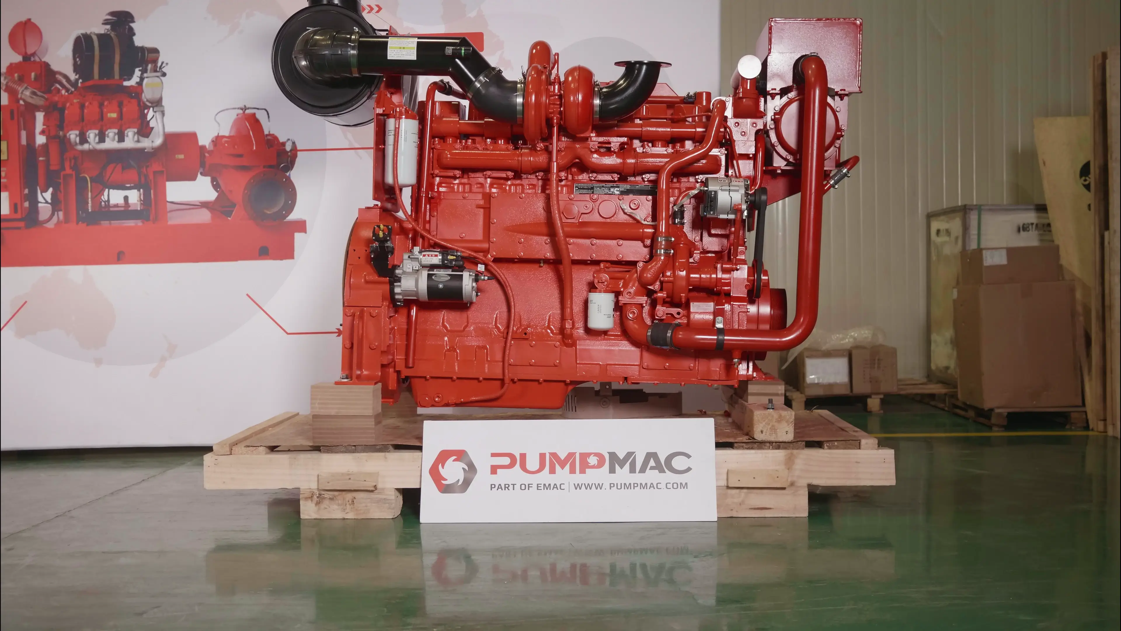
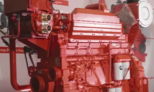
KTA19-P500B Pump Engine
CCEC KTA19-P500B (1800 RPM) Pump Drive Engine is a 6-cylinder inline, 18.9 liters four-strokes engine with 159 mm (6.25 in) bore and 159 mm (6.25 in) stroke.
KTA19-P500B Pump Drive Engine equipped with PT Fuel System, comes with Turbocharger and Water-Air intercooler. The Maximum power at 1800 RPM of CCEC KTA19-P500B pump drive engine is 500 HP (373 kW), The maximum torque of the engine at 1500 RPM is 1575 N.m.
EMAC is a partner of CCEC for many years, we are a professional pump system solution supplier with many years of experience.
We provide customers from all over the world with one-stop pump system solutions from pump system design to pump system supply, from installation to commissioning, and from after-sales. Providing sales service support for spare parts supply, EMAC is your reliable pump system partner, providing you with the best value for money and reliable system solutions.
Advantages of CCEC KTA19-P500B Pump Engine
-
Lower oil consumption, Extended stroke, the expansion of the combustion gas more fully, Increase effective efficiency output, the economy is better.
-
Strong power, advanced 4 air valves structure, greater horsepower, air burning more thoroughly, while making low speed torque increase, quicken response speedily, climb strongly.
-
Excellent reliability, with compulsive cold cut articulated pistons, Can bear extreme high mechanical load and heat load, Strength can be comparable with heavy engine.
-
Better emissions, Decorate injector and symmetrical combustion chamber in center, make the cylinder is more homogeneous mixture, burning more fully, lower emissions.
-
Super life, 30 % engines 800,000 km without overhaul.
-
Excellence power, Clean burning, use the advanced lean-burn closed loop electronic control system.
-
Excellent cold start performance, equipped with air suction electric preheater and 7.8 kW power starter, completely improve the cold start performance of the engine. Through the arctic village-MoHe of China -36 °C extreme low temperature validation.
Technical Specifications
Basic Introduction of CCEC KTA19-P500B Pump Engine
| Engine Model: | KTA19-P500B |
| Engine Type: | 6 Cylinders |
| Displacement: | 1150 in3 / 18.9 L |
| Rated Speed: | 1800 RPM |
| Rated Power / Speed: | 373 kW @ 1800 RPM |
| Aspiration Method: | Turbocharged & Water-Air Intercooler |
| Emission Standard: | Euro I |
| Bore * Stroke: | 6.25 in * 6.25 in / 159 mm * 159 mm |
| Packing Size (L * W * H): | 2142 mm * 1067 mm * 1733 mm |
| Wet Weight: | 1699 kg |
| Lead Time: | 15-30 Working Days |
| Payment Terms: | T/T ,L/C |


Engine Model |
Rated Power |
Aspiration |
Curve & Datasheet |
Compression Ratio |
Fuel System |
| KTA19-P450 | 336 kW (450 HP) @ 2100 RPM | Turbocharged & Water-Air Intercooler | C-4206-B | 15.5 : 1 | PT-STC |
| KTA19-P495 | 369 kW (495 HP) @ 1500 RPM | Turbocharged & Water-Air Intercooler | FR – 4125 | 13.9 : 1 | CMS PT |
| KTA19-P500A | 373 kW (500 HP) @ 1500 RPM | Turbocharged & Water-Air Intercooler | C-432 | 14.5 : 1 | PT-STC |
| KTA19-P500B | 373 kW (500 HP) @ 1800 RPM | Turbocharged & Water-Air Intercooler | C-423 | 14.5 : 1 | PT-STC |
| KTA19-P525A | 392 kW (525 HP) @ 1800 RPM | Turbocharged & Water-Air Intercooler | N/A | 14.5 : 1 | PT-STC |
| KTA19-P525B | 392 kW (525 HP) @ 2100 RPM | Turbocharged & Water-Air Intercooler | C-4205-C | 15.5 : 1 | PT-STC |
| KTA19-P600A | 448 kW (600 HP) @ 1500 RPM | Turbocharged & Water-Air Intercooler | C-433 | 13.9 : 1 | CMS PT |
| KTA19-P600B | 448 kW (600 HP) @ 1800 RPM | Turbocharged & Water-Air Intercooler | FR4706 | 13.9 : 1 | PT-STC |
| KTA19-C600 | 448 kW (600 HP) @ 2100 RPM | Turbocharged & Water-Air Intercooler | C-4129-C | 15.5 : 1 | PT-STC |
| KTA19-P680 | 507 kW (680 HP) @ 1500 RPM | Turbocharged & Water-Air Intercooler | FR | 13.9 : 1 | PT-STC |
| KTA19-P700 | 522 kW (700 HP) @ 1800 RPM | Turbocharged & Water-Air Intercooler | C-437 | 13.9 : 1 | CMS PT |
| KTA19-P750 | 559 kW (750 HP) @ 1800 RPM | Turbocharged & Water-Air Intercooler | FR-4678 | 13.9 : 1 | CMS PT |
| KTA19-P755 | 563 kW (755 HP) @ 1800 RPM | Turbocharged & Water-Air Intercooler | FR-4213 | 13.9 : 1 | CMS PT |
| KTAA19-P673 | 502 kW (673 HP) @ 1500 RPM | Turbocharged & Air-Air Intercooler | FR4596 | 13.9 : 1 | CMS PT |
| KTAA19-C700 | 522 kW (700 HP) @ 2100 RPM | Turbocharged & Air-Air Intercooler | P-4524-B | N / A | N / A |
| KTAA19-P818 | 610 kW (818 HP) @ 1500 RPM | Turbocharged & Air-Air Intercooler | FR4597 | 13.9 : 1 | PT-STC |
| KTAA19-P890 | 664 kW (890 HP) @ 1800 RPM | Turbocharged & Air-Air Intercooler | FR-370 | 13.9 : 1 | CMS PT |
| ——END—— | |||||
General Information of CCEC KTA19-P500B Pump Engine |
|||
| Engine Model | KTA19-P500B | Emission Standard | Euro I |
| Maxi. Rating | 373 kW (500 HP) @ 1800 RPM | Peak Torque | 1575 N.m @ 1500 RPM |
| Curve & Datasheet | C-423 | Displacement | 18.9 L / 1150 in3 |
| Compression Ratio | 14.5 : 1 | Bore * Stroke | 159 mm * 159 mm / 6.25 in * 6.25 in |
| Type | 4 Cycle , In-line , 6 Cylinder | Dry Weight (Fan Hub to Flywheel Engine) | 1633 kg / 3600 lb |
| Fuel System | PT-STC | Wet Weight (Fan Hub to Flywheel Engine) | 1699 kg / 3745 lb |
| Aspiration | Turbocharged & Water-Air Intercooler | Moment of Inertia of Rotating Components (Excluding Flywheel) | 1.82 kg.m2 / 43.2 lbm.ft2 |
| Packing Size (L * W * H) | 2142 mm * 1067 mm * 1733 mm | C.G. Distance From Rear Face of Block (Engine Only) | 572 mm / 22.5 in |
| Configuration | D193034PX02 | C.G. Distance Above Crank Centerline (Engine Only) | 239 mm / 9.4 in |
| CPL Code Revision | 0447 | Maximum Allowable Bending Moment at Rear Face of Block | 1356 N.m / 1000 lb.ft |
| Firing Order | 1-5-3-6-2-4 | Moment of Inertia About Roll Axis | 79 kg·m2 / 1876 lb.ft2 |
Performance Data of CCEC KTA19-P500B Pump Engine |
|||
| Idle | 625 RPM | Crankshaft Thrust Bearing Load — Maximum Intermittent | 6672 N / 1500 lb |
| Maximum No-Load Governed Speed | 1760 RPM | Crankshaft Thrust Bearing Load — Maximum Continuous | 3336 N / 750 lb |
| Starting Torque at Minimum Starting Temperature (Without Auxiliary Devices) | 556 N.m / 410 lb.ft | Maximum Allowable Power From Accessory Drive | 6 kW / 8 HP |
| Recommended Minimum Stall Speed for Torque Converter and Hydraulic Pump | 1800 RPM | ||
| Estimated Free Field Sound Pressure Level— Right Side (At 50 ft(15m) and Full Load Governed Speed (Excludes Noise From Intake.Exhaust. Cooling System and Driven Components) |
82.0 dBA | ||
| Estimated Free Field Sound Pressure Level— Left Side (At 50 ft(15m) and Full Load Governed Speed (Excludes Noise From Intake.Exhaust. Cooling System and Driven Components) |
84.5 dBA | ||
| Estimated Free Field Sound Pressure Level— Front (At 50 ft(15m) and Full Load Governed Speed (Excludes Noise From Intake.Exhaust. Cooling System and Driven Components) |
84.0 dBA | ||
| ——END—— | |||
Performance Data of CCEC KTA19-P500B Pump Engine |
|||||
| Full Power | Peak Torque | Full Power | Peak Torque | ||
| Engine Speed | 1800 RPM | 1500 RPM | Friction Horsepower | 63 kW / 85 HP | 45 kW / 60 HP |
| Gross Power Output | 375 kW / 500 HP | 350 kW / 469 HP | Intake Air Flow | 581 L/s / 1230 CFM | 432 L/s / 915 CFM |
| Torque | 1978 N·m / 1459 lb.ft | 1575 N·m / 2136 lb.ft | Exhaust Gas Flow — Dry Manifold | 1543 L/s / 3270 CFM | 1194 L/s / 2530 CFM |
| Nominal Rail Pressure | 875 kPa / 127 PSI | 745 kPa / 108 PSI | Exhaust Gas Temperatu — Dry Manifold | 493 ℃ / 920 °F | 524 ℃ / 975 °F |
| Intake Manifold Pressure | 129 kPa / 38 in.Hg | 112 kPa / 33 in.Hg | Heat Rejection to Ambient — Dry Manifold | 59 kW / 3380 BTU/min | 50 kW / 2830 BTU/min |
| Brake Mean Effective Pressure | 1386 kPa / 201 PSI | 1427 kPa / 209 PSI | Heat Rejection to Coolant — Dry Manifold | 240 kW / 13650 BTU/min | 206 kW / 11700 BTU/min |
| Piston Speed | 9..5 m/s / 1875 ft/min | 7.9 m/s / 1560 ft/min | Heat Rejection to Coolant — Engine Water Flow | 12.6 L/s / 200 U.S.GPM | 10.1 L/s / 160 U.S.GPM |

System Technical Data of CCEC KTA19-P500B Pump Engine |
|||
| Exhaust System | Maximum Allowable Back Pressure | 10.0 kPa / 3.0 in.Hg | |
| Exhaust Pipe Size Normally Acceptable | 127 mm / 5 in | ||
| Air Induction System | Maximum Allowable Intake Air Restriction With Heavy Duty Air Cleaner — Clean Element | 3.47 kPa / 15 in.H2O | |
| Maximum Allowable Intake Air Restriction With Heavy Duty Air Cleaner — Dirty Element | 6.23 kPa / 25 in.H2O | ||
| Minimum Allowable Dirt Holding Capacity With Heavy Duty Air Cleaner | 53 gm·L/s / 25 gm/CFM | ||
| Cooling System | Coolant Capacity — Engine Only | 30.0 L / 8 U.S.Gal | |
| Coolant Capacity — Radiator With 100 °F | 111.7 L / 29.5 U.S.Gal | ||
| Maximum Coolant Friction Heat External to Engine | 34.5 kPa / 5.0 PSI | ||
| Maximum Static Head of Coolant Above Engine Crank Centerline | 18.3 m / 60 ft. | ||
| Maximum Air Restriction Across Radiator | 0.12 kPa / 0.50 in.H2O | ||
| Minimum Raw Water Flow @ 90 °F(32 ℃) to Heat Exchanger | 208 kPa / 55 PSI | ||
| Maximum Raw Water Inlet Pressure at Heat Exchanger | 689 kPa / 100 PSI | ||
| Standard Thermostat (Modulating) Range | 80-90 ℃ / 175-195 °F | ||
| Maximum Coolant Pressure (Exclusive of Pressure Cap) | 241 kPa / 35 PSI | ||
| Minimum Allowable Pressure Cap | 48 kPa / 7 PSI | ||
| Maximum Allowable Top Tank Temperature | 93.3 ℃ / 200 °F | ||
| Minimum Recommended Temperature for Top Tank | 71.1 ℃ / 160 °F | ||
| Minimum Allowable Fill Rate | 18.9 L/min / 5 U.S.GPM | ||
| Maximum Allowable Initial Fill Time | 5 min | ||
| Minimum Allowable Coolant Expansion Space | 5 % | ||
| Maximum Allowable Deaeration Time | 25 min | ||
| Minimum Allowable Drawdown (Drawdown Must Exceed the Volume Not Filled at Initial Fill & Must Not Include Expansion Space) | 11.4 L / 3.0 U.S.Gal | ||
| Lubrication System | Oil Pressure @ Idle | 138 kPa / 20 PSI | |
| Oil Pressure @ Rated Speed | 345-483 kPa / 50-70 PSI | ||
| Oil Flow at Rated Speed | 151.4 L/min / 40 U.S.GPM | ||
| Maximum Allowable Oil Temperature | 121.1 ℃ / 250 °F | ||
| Maximum Oil Consumption | 0.31 L/min / 0.083 U.S.Gal/h | ||
| By-Pass Filter Capacity — Spin-on Cartridge Type | 2.65 L / 0.7 U.S.Gal | ||
| By-Pass Filter Capacity — Replaceable Element Type | 10.98 L / 2.9 U.S.Gal | ||
| Oil Pan Capacity — High | 37.85 L / 10.0 U.S.Gal | ||
| Oil Pan Capacity — Low | 32.18 L / 8.5 U.S.Gal | ||
| Total System Capacity (Excluding By-Pass Filter) | 47.0 L / 12.5 U.S.Gal | ||
| Angularty of Standard Oil Pan (Option OP4020) — Front Down | 30 ° | ||
| Angularty of Standard Oil Pan (Option OP4020) — Front Up | 30 ° | ||
| Fuel System | Maximum Fuel Consumption at Maximum Rated Output and Speed | 78 kg/h / 172 lb/h | |
| Maximum Fuel Flow to Pump at Maximum Rated Output and Speed | 272 kg/h / 600 lb/h | ||
| Maximum allowable Restriction to PT Fuel Pump — With Clean Fuel Filter | 13.55 kPa / 4 in.Hg | ||
| Maximum allowable Restriction to PT Fuel Pump — With Dirty Fuel Filter | 27.09 kPa / 8 in.Hg | ||
| Maximum Allowable Injector Return Line Restriction — With Check Valves | 22 kPa / 6.5 in.Hg | ||
| Maximum Allowable Injector Return Line Restriction — Less Check Valves | 8.5 kPa / 2.5 in.Hg | ||
| Minimum Allowable Fuel Tank Vent Capability (With 2.5 in. Hg (63 mm Hg) or Less Back Pressure) | 425 L/h / 15 ft3/h | ||
| Electrical System | Minimum Recommended Battary Capacity(Cold Soak at 0 °F(-18 ℃) or Above) | 24 V | |
| Engine Only (De-clutched Load) — Cold Cranking Amperes | 900 CCA | ||
| Engine Only (De-clutched Load) — Reserve Capacity Min | 320 | ||
| Engine With Connected Drive Train — Cold Cranking Amperes | 900 CCA | ||
| Engine With Connected Drive Train — Reserve Capacity Min | 320 | ||
| Maximum Allowable Resistance of Starting Circuit — With 12 Volt Starter | 0.00075 Ω | ||
| Maximum Allowable Resistance of Starting Circuit — With 24 Volt Starter | 0.002 Ω | ||
| ——END—— | |||
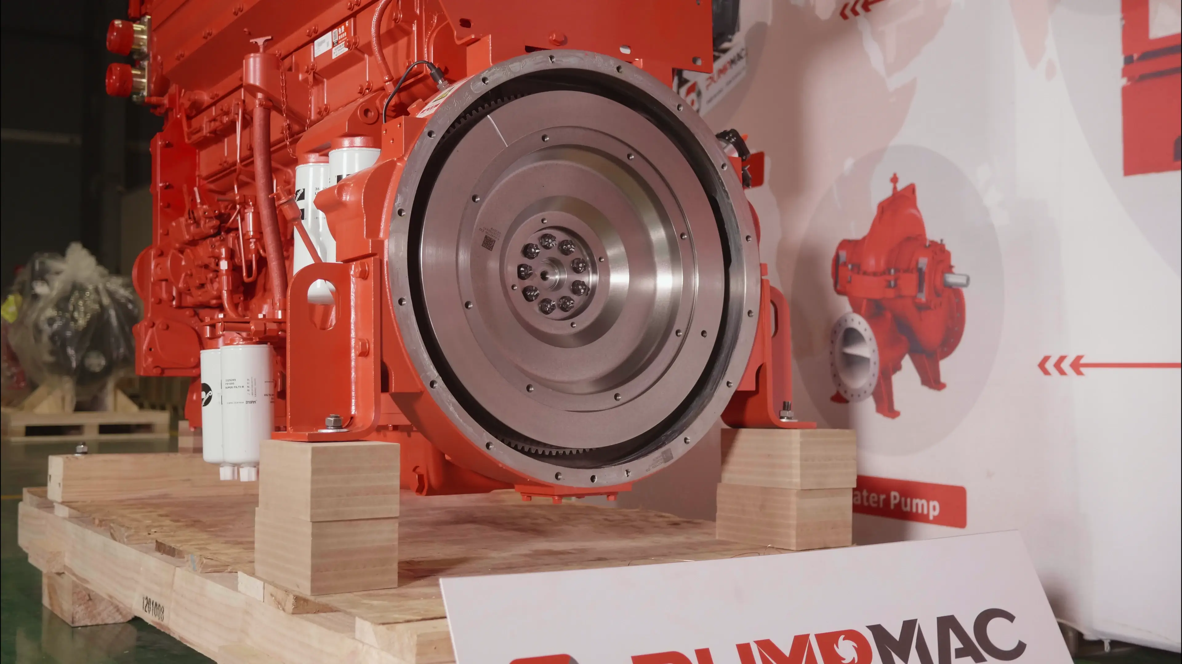
Scopes of Supply of CCEC KTA19-P500B Pump Engine |
|||
| Air Intake System | 1. Air Intake Manifold | Exhuast System | 1. Exhuast Manifold |
| 2. Water-air Intercooler | 2. Turbocharger | ||
| 3. Air Filter | 3. Exhuast Elbow | ||
| Starting System | 1. Starter Motor | Charging System | 1. Charging Alternator |
| 2. Starter Rely | 2. N/A | ||
| Lubricating System | 1. Oil Pump | Fuel System | 1. Fuel Transfer Pump |
| 2. Oil Filter | 2. High-pressure Fuel Pump | ||
| 3. N/A | 3. Fuel Filter | ||
| Engine Shut-Down System | 1. Engine Fuel Shut-off Solenoid | Power Output System | 1. Flywheel |
| 2. N/A | 2. Standard Flywheel Housing | ||
| Control System | 1. Various Engine Speed Controller | Engine Mounting System | 1. Engine Mouting Bracket |
| Cooling System | 1. Water Pump | ||
| 2. Engine Fan | |||
| 3. Standard Radiator | |||
| ——END—— | |||
Optional Accessories of CCEC KTA19-P500B Pump Engine |
|||
| Air Intake System | 1. Air Intake Pre-heater | Exhuast System | 1. Muffler & Bellows |
| 2. Air Intake Pre-filter | 2. Flame Trap | ||
| 3. Air Filter Alarm System | 3. Spark Arrestor Type Muffler & Bellows | ||
| 4.N/A | 4. DPF System | ||
| Fuel System | 1. Coarse Filter | Engine Auiliary Accessories | 1. Hydraulic Oil Pump |
| 2. Fuel Pre-heater | 2. Hydraulic Cluch | ||
| Starting System | 1. Manual Magnetic DC Contactor | Control System | 1. Engine Monitor |
| 2. Dual Ears Flywheel Housing | 2.Engine Protection System with Alarm System | ||
| 3. Spring Starter Motor | 3. Machanical Engine Control Lever System | ||
| 4. Air Starter Motor | 4. Electric Engine Control Lever System | ||
| 5. Hydraulic Starter Motor | 5. N/A | ||
| 6. Manual Magnetic DC Contactor | 6. N/A | ||
| Power Output System | 1. Gear Reduction Gearbox | Cooling System | 1. Coolant Pre-heater |
| 2. Reverse Gear Box | 2. Jacket Water Heater | ||
| Lubricating System | 1. Oil Pre-heater | Engine Mounting System | 1. Shock Absorber Pad |
| ——END—— | |||
As part of EMAC, PumpMac focusing on water pump set related business, from pump drive engine, to WPT PTO, from complete engine power pack to complete water pump set, from NFPA20 standard fire fighting pump accessories to fire pump drive package, from explosion proof accessories to complete explosion-proof water pump set, PumpMac provides professional one-stop solution for everything customer needed for water pump set industry.
For more information of our pump drive power pack and complete water pump set products, you are welcome to visit PumpMac homepage: www.pumpmac.com
Modifiable Components of CCEC KTA19-P500B Pump Engine |
|||
| Air Intake System | 1. Installation Position of Air Filter | Charging System | 1. 12 V Charging Alternator for 12 V Electric System |
| 2. Upgrade to Heavy-duty Type Air Fitler | 2. Explosion-Proof Charging Alternator | ||
| 3. N/A | 3. Upgrading to Specified Brand and Speicifications of Charging Alternator | ||
| Exhuast System | 1. Can Modify Installation Position and Direction of Turbocharger | Lubricating System | 1. Oil Pan Position |
| 2. Water-cooled Exhuast Manifold | 2. Number of Dipstick | ||
| 3. Water-cooled Turbocharger | 3. Position of Dipstick can Choose from 6 Positions | ||
| 4. N/A | 4. Can modify oil filter to be remote installation | ||
| Fuel System | 1. Upgrade to Fuel Fitler that Integrated with Fuel Transfer Pump and Fuel Pre-hearter | Starting System | 1. 12 V Starter Motor for 12 V Electric System |
| 2. N/A | 2. Upgrading to Specified Brand and Speicifications of Starter Motor | ||
| Engine Shut-Down System | 1. 12 V Solenoid for 12 V Electric System | Power Output System | 1. Can Modify Size of Flywheel Housing and Flywheel |
| 2. Explosion-proof Solenoid | 2. Dual-ear Flywheel Housing (For twin-starter System) | ||
| 3. N/A | 3. Some of Models can Modify Flywheel Housing into PTO Integrated Type | ||
| 4. N/A | 4. Engine have Connecting Port of PTOs, that Able to Provide Power Output | ||
| Cooling System | 1. Can Modify Engine into Keel Cooling System | Engine Mounting System | 1. Can Modify Engine Mouting Bracket |
| Engine Auiliary Accessories | 1. Additional Auxiliary Systems can be Added for Special Applications | ||
| ——END—— | |||
Note: All Above Data are Just for Reference, All Data Might Change Without Notices or Updates, Please Contact Our Sales Team to Confirm All Details Via WhatsApp or Email.

Engine Sale Manual

Installation Drawing

Installation Manual

Operation Manual

Parts Catalogue


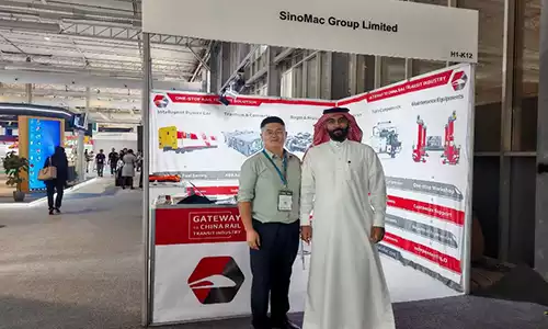
![Deeply Cultivate the International Market, Empowering the Future of Rail ——Focus [PROMotion Expo 2025] SinoMac Exhibition Highlights Review](https://ccec-engine.com/wp-content/uploads/2025/09/Deeply-Cultivate-the-International-Market-Empowering-the-Future-of-Rail-——Focus-PROMotion-Expo-2025-SinoMac-Exhibition-Highlights-Review.webp)