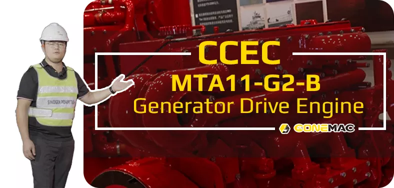
MTA11-G2-B G-Drive Engine
CCEC MTA11-G2-B (1800 RPM) Generator Drive Engine is 6-Cylinder In-line, 10.8 liters (661 in3) Four-Strokes Engine with 125 mm (4.92 in) Bore and 147 mm (5.79 in) Stroke.
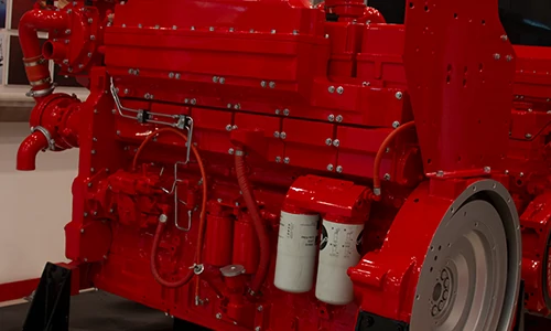
MTA11-G2B Generator Drive Engine Equipped with Direct Injection CMI PT Fuel System, Comes with Turbocharged and Aftercooled.The Standby Power for 60 Hz Generator Set (1800 RPM) of CCEC MTA11-G2-B Generator Drive Engine is 380 HP (283 kW). The Prime Power for 60 Hz Generator Set (1800 RPM) of CCEC MTA11-G2-B Generator Drive Engine is 345 HP (257 kW).The Continuous Power for 60 Hz Generator Set (1800 RPM) of CCEC MTA11-G2-B Generator Drive Engine is 305 HP (227 kW).
As Part of EMAC, SinoGen Also Provide Complete Power Supply Solutions that Powered by CCEC, Our Ranges of Products Including Open Type Generator Set, Silence Type Generator Set, Super Silence Type Generator Set, Mobile Trailer, Complete Power Truck and Complete Power Car for Railways Applications.
We Provide Full Life Cycle Services for All Customers, From Design to Power System Supply, from Installation to Commissioning, from After-Sales Service Training to Spare Parts Supply, From Trouble Shooting to Overhaul Technical Support.
Advantages of CCEC MTA11-G2-B G-Drive Engine
-
High quality alloy cast iron for the rigidity performance and lower vibration and noise. Wet and replaceable cylinder liners for better heat rejection performance and easier replacement.
-
4 valves per cylinder, Optimize the mixed level which lead to an excellent fuel consumption rate and emission performance. High quality alloy cast iron, one cylinder one head, single camshaft and special designed outine for better reliability and durability.
-
CMS unique PT with fixture and Step Timing control for precise fuel injection make the fuel injection pressure above 120 Mpa, which leads to an excellent fuel consumption rate and emission performance. Check valve in fuel tube improve reliability.
-
Gear water pump and great flux channel design provide effective cooling. Spin-in water filter makes the coolant clean and keeps it in normal acidity.
-
Advanced Holset turbocharger and after-cooled technology, pulse exhaust manifold reduce exhaust temperature, provide excellence fuel consumption and emission performance.
Technical Specifications
Basic Introduction of CCEC MTA11-G2-B G-Drive Engine
| Engine Model: | MTA11-G2-B (-B means 1800 RPM engine) |
| Engine Type: | 6 – Cylinder; In – line; 4 – Cycle |
| Displacement: | 10.8 L |
| Rated Power / Speed: | 257 kW @ 1800 RPM |
| Aspiration Method: | TC & Aftercooled Intercooler |
| Emission Standard: | Euro II |
| Bore * Stroke: | 125 mm * 147 mm |
| Packing Size (L * W * H): | 1324 mm * 835 mm * 1183 mm |
| Dry Weight: | 940 kg |
| Lead Time: | 15-30 Working Days |
| Payment Terms: | T / T ,L / C |
Engine Model |
Prime Power |
Standby Power |
Aspiration |
Fuel System |
Performance Curve |
| MTA11-G2-A | 224 kW / 1500 RPM @ 50 Hz | 246 kW / 1500 RPM @ 50 Hz | TC & Aftercooled Intercooler | PT | C – 2487A |
| MTA11-G2-B | 257 kW / 1800 RPM @ 60 Hz | 283 kW / 1800 RPM @ 60 Hz | TC & Aftercooled Intercooler | PT | C – 2487A |
| MTA11-G2A | 234 kW / 1500 RPM @ 50 Hz | 257 kW / 1500 RPM @ 50 Hz | TC & Aftercooled Intercooler | PT | C – 0236A |
| MTAA11-G3 | 282 kW / 1500 RPM @ 50 Hz | 310 kW / 1500 RPM @ 50 Hz | TC & Charged Air Cooled Intercooler | PT | C – 0237A |
| ——END—— | |||||
General Information of CCEC MTA11-G2-B Generator Engine |
|||
| Engine Model | MTA11 – G2B | Configuration | D353009GX03 |
| Performance Curve | C – 2487A | CPL No. | 2165 |
| Type | 6 – Cylinder; In – line; 4 – Cycle | Aspiration | Turbocharged & Aftercooled |
| Bore * Stroke | 125 mm * 147 mm / 4.92 in * 5.79 in | Displacement | 661 in3 / 10.8 L |
| Compression Ratio | 16.1 : 1 | Firing Order | 1 – 5 – 3 – 6 – 2 – 4 |
| Fuel System | PT | Prime Power | 257 kW / 1800 RPM @ 60 Hz |
| Standby Power | 283 kW / 1800 RPM @ 60 Hz | ||
Installation Data of CCEC MTA11-G2-B Generator Engine |
|||
| Wet Weight – Engine Only | 2160 lb / 980 kg | ||
| Dry Weight – Including Flywheel and Generator Excluding other Electrial Component | 2072 lb / 940 kg | ||
| Moment of Inertia of Rotating Components – with FW 2141 Flywheel | 62.4 lbm.ft2 / 2.63 kg.m2 | ||
| Center of Gravity Above Crankshaft Centerline | 7.5 in / 190 mm | ||
| Center of Gravity from Front Face of Block | 17.7 in / 450 mm | ||
| Maximum Bending Moment at Rear Face of Block | 1000 lb.ft / 1356 N.m | ||
| ——END—— | |||
Performance Data of CCEC MTA11-G2-B Generator Engine |
|||||
| Stanby Power | Prime Power | Stanby Power | Prime Power | ||
| Engine Speed | 1800 RPM | 1800 RPM | Engine Idle Speed | 675 – 750 RPM | 675 – 750 RPM |
| Gross Engine Power Output | 283 kW | 257 kW | Brake Mean Effective Pressure | 1742 kPa | 1586 kPa |
| Piston Speed | 8.8 m / s | 8.8 m / s | Friction Horsepower | 30.6 kW | 30.6 kW |
| Intake Air Flow | 380 L / s | 362 L / s | Exhaust Gas Temperature | 440 °C | 429 °C |
| Exhaust Gas Flow | 858 L / s | 802 L / s | Heat Rejection to Ambient | 40 kW | 35 kW |
| Heat Rejection to Coolant | 148 kW | 138 kW | Heat Rejection to Exhaust | 190 kW | 162 kW |
| Engine Water Flow | 5 L / s | 5 L / s | |||

System Technical Data of CCEC MTA11-G2-B Generator Engine |
||
| Exhaust System | Maximum Allowable Exhaust Back Pressure | 3 in Hg / 10 kPa |
| Air Induction System | Maximum Intake Air Restriction – with Dirty Filter Element | 25 in H2O / 6.2 kPa |
| Maximum Intake Air Restriction – with Normal Duty Air Cleaner and Clean Filter Element | 10 in H2O / 2.5 kPa | |
| Maximum Intake Air Restriction – with Heavy Duty Air Cleaner and Clean Filter Element | 15 in H2O / 3.7 kPa | |
| Coolig System | Coolant Capacity – Engine Only | 3.4 US gal / 12.9 L |
| Maximum Coolant Friction Head External to Engine – 1800 RPM | 6 PSI / 41 kPa | |
| Maximum Coolant Friction Head External to Engine – 1500 RPM | 5 PSI / 34 kPa | |
| Maximum Static Head of Coolant Above Engine Crank Centerline | 46 ft / 14 m | |
| Standard Thermostat (Modulating) Range | 180 – 200 °F / 82 – 94 °C | |
| Minimum Pressure Cap | 7 PSI / 50 kPa | |
| Maximum Top Tank Temperature for Standby / Prime Power | 220 / 212 °F / 104 / 100 °C | |
| Lubrication System | Oil Pressure @ Idle Speed | 10 PSI / 69 kPa |
| Oil Pressure @ Governed Speed | 30 – 50 PSI / 207 – 345 kPa | |
| Maximum Allowable Oil Temperature | 250 °F / 121 °C | |
| Oil Capacity with OP 2152 : Low – High | 7/9 US gal / 26.5/34 L | |
| Total System Capacity (with LF9009 Combine Filter) | 9.7 US gal / 36.7 L | |
| Angularity of OP2152 Oil Pan – Rear Down | 45 ° | |
| Angularity of OP2152 Oil Pan – Front Down | 42 ° | |
| Angularity of OP2152 Oil Pan – Exhaust Side Down | 45 ° | |
| Angularity of OP2152 Oil Pan – Fuel Pump Side Down | 40 ° | |
| Fuel System | Type Injection System | Direct Injection Cummins PT |
| Maximum Allowable Restriction to Fuel Pump – with Clean Fuel Filter | 4 in Hg / 13.3 in Hg | |
| Maximum Allowable Restriction to Fuel Pump – with Dirty Fuel Filter | 8 in Hg / 26.7 in Hg | |
| Maximum Allowable Head on Injector Return Line – With Check Valve | 6.5 in Hg / 22 kPa | |
| Maximum Allowable Head on Injector Return Line – Without Check Valve | 2.5 in Hg / 8.5 kPa | |
| Electrical System | Standard Cranking Motor (Heavy Duty, Positive Engagement) | 24 Volt |
| Standard Battery Charging System , Negative Ground | 35 ampere | |
| Maximum Allowable Resistance of Cranking Circuit | 0.002 Ω | |
| Minimum Recommended Battery Capacity – Cold Soak @ 50 °F (10 °C) and Above | 6000 °F CCA | |
| Minimum Recommended Battery Capacity – Cold Soak @ 32 °F to 50 °F (0 °C to 10 °C) | 6400 °F CCA | |
| Minimum Recommended Battery Capacity – Cold Soak @ 0 °F to 32 °F (-18 °C to 0 °C) | 9000 °F CCA | |
| Cranking System | Minimum Cranking Speed Required for Unaided Cold Start | 150 RPM |
| ——END—— | ||
Scopes of Supply of CCEC MTA11-G2-B Generator Drive Engine |
|||
| Air Intake System | 1. Air Intake Manifold | Exhuast System | 1. Exhuast Manifold |
| 2. Standard Air Filter | 2. Turbocharger | ||
| 3. Water-Air Intercooler | 3. Exhuast Elbow | ||
| Starting System | 1. Starter Motor | Charging System | 1. Charging Alternator |
| 2. Starter Rely | |||
| Lubricating System | 1. Oil Pump | Cooling System | 1. Water Pump |
| 2. Oil Filter | 2. Engine Fan | ||
| 3. Standard Radiator | |||
| Engine Shut-Down System | 1. Engine Fuel Shut-Off Solenoid | Power Output System | 1. Flywheel |
| 2. Standard Flywheel Housing | |||
| Fuel System | 1. Fuel Transfer Pump | ||
| 2. High-Pressure Fuel Pump | |||
| 3. Fuel Filter | |||
| ——END—— | |||
Optional Accessories of CCEC MTA11-G2-B Generator Drive Engine |
|||
| Air Intake System | 1. Air Intake Pre-Heater | Exhuast System | 1. Muffler & Bellows |
| 2. Air Intake Shut-Off Valve | 2. Spark Arrestor Type Muffler & Bellows | ||
| 3. Heavy-Duty Air Filter | 3. DPF System | ||
| 4. Plateau Type Air Filter | |||
| Fuel System | 1. Coarse Filter | Lubricating System | 1. Oil Pre-Heater |
| 2. Fuel Pre-Heater | |||
| Starting System | 1. Manual Magnetic DC Contactor | Cooling System | 1. Silent Type Radiator |
| 2. Dual Ears Flywheel Housing | 2. Plateau Radiator | ||
| 3. Spring Starter Motor | 3. Salt-Spray Resistant Radiator | ||
| 4. Air Starter Motor | 4. Coolant Pre-Heater | ||
| 5. Hydraulic Starter Motor | 5. Jacket Water Heater | ||
| 6. Manual Magnetic DC Contactor | |||
| ——END—— | |||
As part of EMAC, SinoGen focusing on generator set related business, from Generator drive engine power pack to complete generator set, from generator control panel to synchronizing cabinet, from super silent type generator set to mobile power trailer, SinoGen provides professional one-stop solution for everything customer needed for generator set.
For more information of our complete generator set products, you are welcome to visit SinoGen homepage: www.sino-gen.com
Modifiable components of CCEC MTA11-G2-B Generator Drive Engine |
|||
| Air Intake System | 1. Installation Position of Air Filter | Charging System | 1. 12 V Charging Alternator for 12 V Electric System |
| 2. Upgrade to Heavy-Duty Type Air Fitler | 2. Explosion-Proof Charging Alternator | ||
| Exhuast System | 1. Position of Turbocharger | Lubricating System | 1. Oil Pan Position |
| 2. Water-Cooled Exhuast Manifold | 2. Number of Dipstick | ||
| 3. Water-Cooled Turbocharger | 3. Position of Dipstick | ||
| Fuel System | 1. Upgrade to Fuel Fitler that Integrated with Fuel Transfer Pump | Starting System | 1. 12 V Starter Motor for 12 V Electric System |
| Engine Shut-Down System | 1. 12 V Solenoid for 12 V Electric System | Power Output System | 1. Size of Flywheel Housing and Flywheel. |
| 2. Explosion-Proof Solenoid | 2. Dual-Ear Flywheel Housing (For Twin-Starter System) | ||
| ——END—— | |||
Note: All Above Data are Just for Reference, All Data Might Change Without Notices or Updates, Please Contact Our Sales Team to Confirm All Details Via WhatsApp or Email.

Engine Sale Manual

Installation Drawing

Installation Manual

Operation Manual

Parts Catalogue


![Deeply Cultivate the International Market, Empowering the Future of Rail ——Focus [PROMotion Expo 2025] SinoMac Exhibition Highlights Review](https://ccec-engine.com/wp-content/uploads/2025/09/Deeply-Cultivate-the-International-Market-Empowering-the-Future-of-Rail-——Focus-PROMotion-Expo-2025-SinoMac-Exhibition-Highlights-Review.webp)